
Install Instructions

1-550.26
hot water systems, include a balancing valve in return line for
water flow regulation. A drain valve should also be provided
below each unit heater to allow removal of water from the
heating coil if located in an area subject to freezing.
3. In steam or hot water systems, rapid air removal is required
because entrained air is a cause of corrosion. Hot water
systems should be equipped with suitable air vent valves for
rapid and complete removal of air at the high points and ends
of both supply and return mains. Proper air venting for steam
systems can be achieved by use of a steam trap with an
internal air vent.
4. Traps must be located below the outlet of the unit. Consult
trap manufacturer for specific recommendations. Each steam
unit heater should be provided with a trap of sufficient size
and capacity to pass a minimum of two times the normal
condensate released by the unit at the minimum differential
pressure in the system. Trap capacity is based on the
pressure differential between supply and return mains. Steam
systems should be equipped with a float and thermostatic
trap or an inverted bucket trap with an air bypass.
5. It is advisable to use a pipe line strainer before each steam
trap draining a unit heater. This protection will reduce the
maintenance of the steam trap. When strainers are used they
should be installed between the unit heater and the trap and
be the same size as the trap tapping. In order to catch dirt
and scale, the strainer should have a screen perforation size
smaller than the trap orifices.
6. On systems where the steam supply to the unit heater is
modulated or controlled by a motorized valve, a vacuum
breaker should be installed between unit outlet and the trap.
If a vacuum breaker is used, it should be in conjunction with
a float and thermostatic trap.
7. Install a scale pocket at bottom of unit heater to collect dirt
and scale as shown in illustrations. Pipe diameter must be
the same size as unit connections and about six inches long.
8. Provide adequate pipe hangers, supports, or anchors to
secure the piping system independently of the unit heater.
Electrical Connections
1. Installation of wiring must conform with local building
codes, or in the absence of local codes, with the National
Electric Code ANSI/NFPA 70 - Latest Edition. Unit must be
electrically grounded in conformance to this code. In Canada,
wiring must comply with CSA C22.1, Electrical Code.
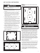
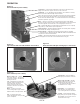
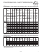
Figure 5.1
Unit Suspension
UNIT SUSPENSION
Horizontal delivery units, Model HSB/HC Series. All horizontal
delivery units, except Models HSB-18 and HSB-24, have two
tapped holes in the top for unit suspension. HSB-18 and HSB-24
models do not require independent suspension and are installed
directly on their supply piping. Models HSB 33-86 and HC 18-86
have 3/8"-16 tapped holes, model sizes 108 and larger have
1/2"-13 tapped holes. Piping support hangers or clamps are
recommended and should be placed as close to the unit heater
as possible. For other models, independent suspension can be
made with threaded rods, pipes, or ceiling hanger brackets. See
Figure 5.1.
Vertical delivery units. Vertical delivery Models V/VN-42
through V/VN-279 have four tapped holes (1/2"-13) in the top
cover for unit suspension. Unit suspension for these models can
be made with threaded rods, pipes or ceiling hanger brackets.
Models V/VN-333 through V/VN-952 are equipped with an angle-
iron mounting bracket that has eight 5/8-inch diameter hanger
holes permitting hook-hoisting and suspension with cables,
if desired. A 1/2-inch U-bolt, 3-inch center can be inserted in
the two holes at each end of the bracket to accommodate
suspension with four threaded rods, pipes or hanger brackets.
Power-Throw horizontal delivery units. “Power-Throw” units
are designed for horizontal air delivery and are equipped with
hanger brackets for suspension. Three hanger brackets are
supplied for Model PT/PTN-279, one on the front, and two on the
rear panel for three-point suspension. Only two hanger brackets
are furnished on the front panel of Models PT/PTN-333 through
PT/PTN-952 (for required four-point suspension use the two
hanger brackets on the front panel and the two holes on the
ends of the upper angle supports at the rear of the unit). Each
hanger bracket has a 5/8-inch diameter mounting hole for hook-
hoisting and suspension with threaded rods, pipes, or cables.
Note: A pipe hanger adapter kit as illustrated in Figure 5.1 is
available as an accessory from Modine. The kit consists of two
drilled 3/4-inch I.P.S. pipe caps and two capscrews to facilitate
threaded-pipe suspension. One kit will mount applicable HSB or
HC models, two kits are required for V/VN models.
UNIT SUSPENSION / INSTALLATION
wARNINg
1. Disconnect power supply before making wiring connections
to prevent electrical shock and equipment damage.
2. All appliances must be wired strictly in accordance with
wiring diagram furnished with the appliance. Any wiring
different from the wiring diagram could result in a hazard
to persons and property.
3. Any original factory wiring that requires replacement must
be replaced with wiring material having a temperature
rating of at least 105°C.
4. Ensure that the supply voltage to the appliance as indicated
on the serial plate is not 5% greater than the rated voltage.
5
CAuTION
1. Do not install units below 8 feet measured from the bottom
of the unit to the floor.
2. Do not reuse any electrical component which has been
wet. Such component must be replaced.
3. Ensure that the supply voltage to the appliance, as indicated
on the serial plate is not 5% less than the rated voltage.
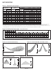
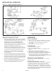
Piping - See Figure 6.1
1. Branch piping to and from unit heater should include swing
joints to allow for expansion and contraction of the piping
without placing a strain on the unit heater element. On steam
systems, the branch piping should be taken off and returned
above the centerline of the supply and return lines.
2. Install pipe unions and shut-off valves in lines to and from
each unit heater to allow maintenance or replacement of
unit without shutting down and draining entire system. For