
Wiring Guide


6-461.1
September, 2009
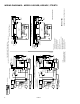
WIRING DIAGRAMS
gas-fired, power vented and separated combustion unit heaters
for models HD/HDB, HDS/HDC, PTS/BTS, PTC
THIS MANUAL IS THE PROPERTY OF THE OWNER.
PLEASE BE SURE TO LEAVE IT WITH THE OWNER WHEN YOU LEAVE THE JOB.
Modine Manufacturing Company has a continuous product improvement program,
and therefore reserves the right to change design and specifications without notice.
WARNING
1. Fuel supply shall be shut-off and the electrical power
disconnected before proceeding with the installation.
Failure to do so could result in fire, explosion, electrical
shock, or the unit starting suddenly resulting in injury.
2. All units must be wired strictly in accordance with wiring
diagram furnished with the unit. Failure to wire this unit
according to this wiring diagram could result in a hazard
to persons and property. For deviations, contact the
factory.
3.
All wiring must be done with a wiring material having a
temperature rating of at least 105°C.
IMPORTANT
1. The use of this manual is specifically intended for a
qualified installation and service agency. All installation
and service of these kits must be performed by a qualified
installation and service agency.
2. These instructions must also be used in conjunction with
the Installation and Service manual originally shipped
with the appliance being converted, in addition to any
other accompanying component supplier literature which
supersedes these instructions.
Diagram Selection
Diagrams are provided for both single and three-phase
circuits, and are readily identified in the selection table on
page 2. The selection table enables easy selection of the
correct wiring diagram after the electrical components of the
unit heater have been determined.
NOTE: As indicated in every diagram, all wiring must
comply with the National Electrical Code and all local codes.
All components must agree with their respective power
source.
Abbreviations and Symbols
To facilitate interpretation and enable simplification the abbreviations
and symbols have been selected as recommended by ANSI
(American National Standards Institute) and NEMA (National
Electrical Manufacturers Association) standards.
XFMR or TR Transformer
H1, H2, etc. Transformer Primary Terminals
X1, X2, etc. Transformer Secondary Terminals
V Volts
Hz Hertz
ø Phase
RC Relay Contactor Coil
G Ground
H Hot
SW Switch
HI High
LO Low
C Common
“J” Box Junction Box
S/W Summer/Winter Switch
O.L.C. Overload Contacts
SPDT Single Pole Double Throw Switch
DPDT Double Pole Double Throw Switch
VA Volt-Ampere
L1, L2, L3 Load Terminals (Connect to Supply Voltage)
T1, T2, T3 Motor or Motor Starter Terminals
Wire Color Coding
BK Black
BR Brown
BL Blue
R Red
W White
GY Gray
Y Yellow