
Use and Care Manual


11
6-583.8
Fan+
Nat
Area of Common Vent
4 in. 5 in. 6 in. 7 in.
Additional Requirements for Common Venting:
1. The common vent system and all attached appliances must
be Category I.
2. The vent connector should be routed in the most direct
route from the units to the common vent.
3. Where 2 or more vent connectors enter a common gas
vent or chimney flue, the smaller connector shall enter at
the highest level consistent with the available head room or
clearance to combustible material.
4. Restrictions within the common vent such as elbows should
be minimized. Each elbow installed within the common
portion of the venting system reduces maximum common
vent capacity by 10% (refer to Tables 11.2 and 11.3 for
capacity).
5. The vent connector capacities included in these tables allow
for the use of two 90° elbows (or turns). For each additional
elbow, the vent connector capacity shall be reduced by
10%. Refer to NFPA54/ IFEC tables for capacity ratings.
6. The common vent cross sectional area must be equal to or
greater than the largest vent connector cross-sectional area.
7. If all appliances are located on one level of the building, the
vent height shall be measured from the highest draft hood
or vent connector to be installed within the common vent
system (refer to Figures 11.1 and 11.2).
8. All units must be vented in strict accordance of the common
venting Tables 11.1 through 11.3.
9. All masonry chimneys must comply with all applicable local
and national codes.
10. When combining multiple vent connectors into a manifold
prior to the vertical portion of the common vent, the size of
the common vent manifold and the common vent shall be
determined by applying a 10% reduction (.90 x maximum
vent capacity from Table 11.2 or 11.3) to the common vent
capacity part of the common vent tables. The length of the
common vent manifold (Lm) may not exceed 18 inches per
inch of manifold diameter.
11. Refer to the National Fuel Gas Code for instructions on
multi-level common venting and exterior masonry chimneys
as well as additional installation of the listed applications.
INSTALLATION - VENTING
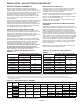
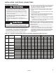
Table 11.2 - Maximum Total Appliance Input Capacities
(MBh) - Type B Vent Connector and Type B Common
Vent
Vent
Height
(ft)
Diameter of Common Vent
6 92 81 140 116 204 161 309 248
8 101 90 155 129 224 178 339 275
10 110 97 169 141 243 194 367 299
15 125 112 195 164 283 228 427 352
20 136 123 215 183 314 255 475 394
30 152 138 244 210 361 297 547 459
Fan+ Fan+ Fan+ Fan+ Fan+ Fan+ Fan+ Fan+
Fan Nat Fan Nat Fan Nat Fan Nat
Based on ANSI Z223.1 (NFPA 54)-2009. For reference only.
Based on ANSI Z223.1 (NFPA 54)-2009. For reference only.
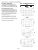
Table 11.3 - Maximum Total Appliance Input
Capacities (MBh) - Type B Vent Connector with
Common Vent into Masonry Chimney
Vent
Height
(ft.)
12 in
2
19 in
2
28 in
2
38 in
2
6 NA 74 NA 119 NA 178 NA 257
8 NA 80 NA 130 NA 193 NA 279
10 NA 84 NA 138 NA 207 NA 299
15 NA NA NA 152 NA 233 NA 334
20 NA NA NA NA NA 250 NA 368
30 NA NA NA NA NA 270 NA 404
Fan+
Fan
Fan+
Nat
Fan+
Fan
Fan+
Nat
Fan+
Fan
Fan+
Nat
Fan+
Fan
Based on ANSI Z223.1 (NFPA 54)-2009. For reference only.
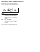
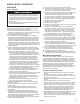
Connector
Dia.
Model Max Horiz. Run
3" 30,45,60,75 4.5
4" 100, 125 6
Table 11.1 - Maximum Vent Connector Horizontal
Run (ft) - Type B Vent Connector
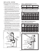
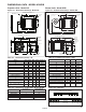
Figure 11.1 - Common Venting into Double Wall B Vent
Figure 11.2 - Common Venting into Masonry Chimney
USE THIMBLE
THROUGH CELLING
TEE WITH DRIP
LEG AND
CLEANOUT CAP
RECOMENDED
LISTED TERMINAL
UPWARD SLOPE VENT
1/4" PER FOOT TOWARDS DRIP LEG
USE LISTED
THIMBLE
FLASHING
CATEGORY I APPLIANCE
TYPE B DOUBLE WALL
VENT CONNECTOR
TYPE B DOUBLE WALL
COMMON VENT
12" MIN.
REC.
3' MAX
VENT HEIGHT
UPWARD SLOPE VENT
1/4" PER FOOT TOWARDS CHIMNEY
FLASHING
CATEGORY I APPLIANCE
TYPE B DOUBLE WALL
VENT CONNECTOR
MASONRY CHIMNEY
(COMMON VENT)
3' MAX
CHIMNEY
HEIGHT