
Use and Care Manual


20
6-583.8
SERVICE / MAINTENANCE / TROUBLESHOOTING
General Maintenance
The unit and venting system must be checked once a year by a
qualified service technician.
All installation and service of these units must be
performed by a qualified installation and service agency.
Before any service, BE SURE TO TURN OFF GAS AT THE
MANUAL SHUT-OFF VALVE AHEAD OF THE COMBINATION
GAS CONTROL AND TURN OFF ALL ELECTRIC POWER TO
THE HEATER.
1. Service air moving components annually.
a. Check fan for fit on motor shaft and for damage to blades.
2. Keep unit free from dust, dirt, grease, and foreign matter,
paying particular attention to:
a. Combustion air inlets.
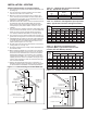
b. Burners and burner orifices. Turn off gas ahead of the
combination gas control and shut off electric power to
the heater. Remove the access panel, open the union
on the gas line, and disconnect the igniter and sensor
wires. Remove the screws that attach the burner tray to
the header plate and remove the burner tray and manifold
assembly from the heater. Carefully clean the burners
with a wire brush or other suitable means. Replace any
damaged or deteriorating burners or orifices. Install the
burner assembly back on to the header making certain that
all screws, pipes and electrical connections are tight.
CAUTION: Be careful when handling the igniter and flame
sensor.
3. Inspect the flame sensor and igniter for deterioration and/or
cracks.
4. Verify that the burners are touching each other at the
carryover points. This will ensure flame carryover from burner
to burner.
a. Clean exterior of heat exchanger tubes.
b. Fan blades.
5. Check wiring for possible loose connections.
6. Controls – The gas valves and piping should be checked
annually for general cleanliness and tightness. The gas
controls should be checked to insure that the unit is operating
properly. See control instruction sheets furnished separately
with the unit heater.
7. Power exhaust assembly/motor – The power exhaust motor
bearings have been lubricated for long life and do not
require additional lubrication. In dirty environments, it may be
desirable to clean the motors and blower housing and blow
out the cooling air passages of the motor with compressed air.
8. Perform periodic cleaning of inlet and vent terminal screens.
cAUTION
1. Service or repair of this equipment must be performed by a
qualified service agency.
2. Do not attempt to reuse any mechanical or electrical
controllers which have been wet. Replace defective controller.
WARNING
When servicing or repairing this equipment, use only factory-
approved service replacement parts. A complete replacement
parts list may be obtained by contacting the factory. Refer
to the rating plate on the appliance for complete appliance
model number, serial number, and company address. Any
substitution of parts or controls not approved by the factory
willbeattheowner’srisk.
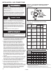
IMPORTANT
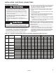
To check most of the Possible Remedies in the troubleshooting
guide listed in Table 20.1, refer to the applicable sections of
the manual.
Table 20.1 - Troubleshooting
TROUBLE POSSIBLE CAUSE POSSIBLE REMEDY
Unit does nothing 1. Power supply is off 1. Turn on main power
2. No 24V power to thermostat 2 a. Check control transformer
b. If failed transformer - check thermostat wire gage and length
3. Thermostat malfunction 3 a. Verify wire connections to R&W terminals only
b. Check / replace thermostat
4. LED flashes 4. Check LED flash code
5. Blown fuse on control board 5. Replace fuse
6. Defective control 6. Replace control
LED light off or 1. Blown fuse on control board 1. Replace fuse
flashing 2. Multiple causes 2. Control board LED flash codes vary with control type. A decal is
installed in the unit giving a brief description of the applicable codes
for your heater. For more detail, see the control board data sheet
included with the unit.
Unit starts but does 1. Main gas is off 1. Open manual gas valve
not ignite 2. Air in gas line 2. Purge gas line
3. Main or manifold gas pressure 3. Set gas pressures per manual instructions
4. Check gas valve switch 4. Set gas valve switch to “ON” position
Unit goes through cycle 1. Reversed main power polarity 1. Black wire - HOT, White wire - NEUTRAL, Green wire - GROUND
but the burners go out 2. Unit not grounded 2. Ground unit and verify quality of ground connection
in less then 10 seconds 3. Flame not sensed 3. Check flame sense probe and connection
Air circulating fan 1. Loose connections 1. Check all connections
inoperable 2. Defective control board 2. Check control board data sheet and function
3. Defective fan motor 3. Check fan motor