
Instructions / Assembly

15
6-583.11
INSTALLATION - ELECTRICAL CONNECTIONS
ELECTRICAL CONNECTIONS
1. Disconnect power supply before making wiring connections
to prevent electrical shock and equipment damage.
2. All appliances must be wired strictly in accordance with
wiring diagram furnished with the appliance. Any wiring
different from the wiring diagram could result in a hazard
to persons and property.
3. Any original factory wiring that requires replacement must
be replaced with wiring material having a temperature
rating of at least 105°C.
4. Ensure that the supply voltage to the appliance, as
indicated on the serial plate, is not 5% greater than rated
voltage.
CAUTION
Ensure that the supply voltage to the appliance, as indicated
on the serial plate, is not 5% less than the rated voltage.
1. Installation of wiring must conform with local building codes,
or in the absence of local codes, with the National Electric
Code ANSI/NFPA 70 - Latest Edition. Unit must be electri cally
grounded in conformance to this code. In Canada, wiring
must comply with CSA C22.1, Part 1, Electrical Code.
2. Two copies of the unit wiring diagram are provided with each
unit. One is located in the side access control compartment
and the other is supplied in the literature packet. Refer to this
diagram for all wiring connections.
3. Make sure all multi-voltage components (motors, transform-
ers, etc.) are wired in accordance with the power supply
voltage.
4. The power supply to the unit must be protected with a fused
or circuit breaker switch.
5. The power supply must be within 5 percent of the voltage
rating and each phase must be balanced within 2 percent of
each other. If not, advise the utility company.
6. External electrical service connections that must be installed
include:
a. Supply power connection (115, 208, 230, 460, or 575 volts).
b. Connection of thermostats, or any other accessory control
devices that may be supplied (24 volts).
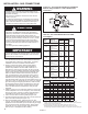
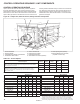
NOTE: All units with supply voltage 208V and greater must use
a field installed step-down transformer, available as a separate
accessory. Refer to Table 15.1 for additional information on the
required transformer.
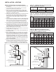
7. Refer to Figures 18.1 and 18.2 for the side access control
compartment location.
8. All supply power electrical connections are made in the side
access control compartment of the unit. The low voltage
(thermostat and accessory control devices) can be wired to
the terminals in the side access control compartment. Refer
to the wiring diagram for the terminal location of all low
voltage wiring.
W
ARNING