
IPT Installation Manual


4
9-511.4
Location Recommendations
1. When locating the heater, consider the general space and
heating requirements and availability of gas and electrical
supply.
2. Be sure the structural support and chain at the unit location is
adequate to support the weight of the unit.
3. Be sure that the minimum clearances to combustible
materials and are maintained. The minimum clearances to
combustibles are shown in Table 4.1, and Figures 4.1 and
4.2, as well as affixed to the burner Model Identification plate.
4. Maintain a recommended minimum of 18" clearance from the
access side of the burner box and also on the combustion air
inlet end of the burner box.
5. Mounting height (measured from the bottom of unit) at which
heaters are installed is important to maintain proper occupant
comfort levels. Please refer to mounting height information in
Table 21.1.
6. Do not locate units in areas where chlorinated, halogenated,
or acid vapors are present in the atmosphere.
7. Unit gas control can be field configured for right or left access,
depending on unit location. See general instructions for
"Rotation of Gas Control" on page 5.
Combustion Air Requirements
Units installed in tightly sealed buildings or confined spaces
must be provided with two permanent openings, one near the
top of the confined space and one near the bottom. Each
opening should have a free area of not less than one square
inch per 1,000 BTU per hour of the total input rating off all units
in the enclosure, freely communicating with interior areas
having, in turn adequate infiltration from the outside.
For further details on supplying combustion air to a confined
(tightly sealed) space or unconfined space, see the National
Fuel Gas Code ANSI Z223.1 of CAN/CGA B149.1 or .2
Installation Code, latest edition.
An accessory combustion air intake collar can be used to bring
outside combustion air to the unit using 4" pipe. Refer to the
venting section "Utilizing Outside Combustion Air" on page 14
for details on pipe length and location.
Clearance to Combustibles
Ensure that:
1. Clearances to combustibles (as shown on the Model
Identification plate and in Table 4.1) are maintained. These
Clearances also apply to vehicles parked below the heater.
2. Adequate clearances to sprinkler heads are maintained. As a
guideline, certified minimum distance to combustible material
is based on the combustible material surface not exceeding
90˚Faboveambient(160˚Ftypical).
3. The stated clearance to combustibles represents a surface
temperature of 90°F (50°C) above room temperature.
Building materials with a low heat tolerance (such as plastics,
vinyl siding, canvas, tri-ply, etc.) may be subject to
degradation at lower temperatures. It is the installer's
responsibility to assure that adjacent materials are protected
from degradation.
Storage of Combustible Materials
In locations used for storage of combustible materials, signs
shall be clearly posted in the vicinity of the heater where readily
apparent to material handlers to specify the maximum
permissible stacking height to maintain required clearances from
the heater to the combustibles. See Figure 4.3.
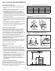
UNIT LOCATION /AIR REQUIREMENTS
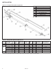
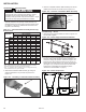
Combustible Material Clearances (inches)
Input MBH “A”
➀ “B” “C”
50/60 9 54 20
75/100/125 9 76 24
150/175/200 12 106 38
➀ Clearance to each end and above the U-Tube is 12 inches.
Refer to Figures 4.1 and 4.2.
Table 4.1 - Combustible Material Clearances (inches) ➀
"U" TUBE
"B"
"C"
"A"
"B"
"A"
0° MOUNTING ANGLE
"B"
"B"
"C"
"C"
"C"
"A"
"C"
"C"
"B"
"B"
"U" TUBE
CHAIN LOCATION
CHAIN LOCATION
CHAIN LOCATION
45° MOUNTING ANGLE
(MAXIMUM)
0° MOUNTING ANGLE
12"
45° MOUNTING ANGLE
(MAXIMUM)
"A"
"A"
Figure 4.1 - Combustible Material Clearances -
Straight Tube
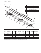
"U" TUBE
"B"
"C"
"A"
"B"
"A"
0° MOUNTING ANGLE
"B"
"B"
"C"
"C"
"C"
"A"
"C"
"C"
"B"
"B"
"U" TUBE
CHAIN LOCATION
CHAIN LOCATION
CHAIN LOCATION
45° MOUNTING ANGLE
(MAXIMUM)
0° MOUNTING ANGLE
12"
45° MOUNTING ANGLE
(MAXIMUM)
"A"
"A"
Figure 4.2 - Combustible Material Clearances -
U-Tube
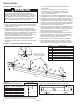
Mounting
Height
Minimum Clearance to
Combustible Materials
Stacking
Height
Unit Heater
Figure 4.3 - Stacking Height