
IPT Installation Manual


5
9-511.4
INSTALLATION
1. Be sure the method of unit suspension is adequate to support
the weight of the burner and tube system (see Tables 18.1
and 18.2 for system weights).
2. Combustible material and service clearances as specified in
Table 4.1 and Figures 4.1 through 4.3 must be strictly
maintained.
3. Maintain a recommended minimum of 18" clearance from the
access side of the burner box and also on the combustion air
inlet end of the burner box.
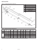
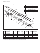
4. Before installing, review the components to be installed
against Figure 6.1 and Table 6.1 for straight tube systems or
Figure 7.1 and Table 7.1 for U-Tube systems. Ensure that all
parts are identified and available before proceeding with
installation of the unit.
5. It is recommended that the uninstalled system components
be arranged on the floor, where possible, to match the
intended layout. This can help ensure the layout matches the
intended design.
6. The standard gas control access is on the left side when
looking at the back end of the burner (combustion air inlet
end). If the intended installation requires access from the
opposite side, please follow the instructions in the section
titled "Rotation of Gas Control" prior to burner installation.
7. For proper operation, the burner and tube system must be
installed in a level horizontal position. Use a spirit level during
installation to ensure that the unit is suspended level.
8. Under no circumstances should the gas supply line or the
electrical supply line to the heater provide any assistance in
the suspension of the heater. Do not locate any gas or
electric service line directly above or below the heater.
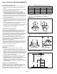
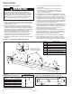
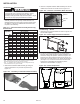
Removal of Burner Side Access Panels
Each of the two side access panels are held in place by two (2)
screws, as shown in Figure 5.1. Once the screws are removed,
the panels slide down, where they can either hang on the
hooks shown in Figure 22.1 or be removed completely during
service or maintenance. The unit is designed to operate without
these panels in place so that adjustments of the controls can
be made. The panels must be returned to the unit once
installation is complete.
Remove Screws (2)
Side Access
Panel
Figure 5.1 - Side Access Panels
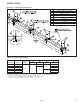
Unit Mounting – Pre-Installation Notes
This section is only required if opposite side gas control access
is required. The standard access is on the left side when looking
at the back of the burner box (combustion air inlet end).
In order to install the heater so that the gas valve's controls can
be accessed from the opposite side of the burner box, the valve
may be rotated 180° by following the procedure below.
1. Remove burner side access panels as described in the
previous section.
2. Unplug all wires from the valve.
3. Using two wrenches, loosen the factory-supplied union in
the burner box and remove the gas valve. Do not apply
the wrenches directly to either the gas valve or the
gas manifold.
4. Remove the plug from the factory-supplied "tee" fitting and
screw it into the opposite leg of the tee. Be sure to properly
seal the threads of this connection.
5. Seat the gas valve onto the factory-supplied union, so that
the valve faces the opposite side of the burner box.
Tighten the union using two wrenches, without applying
them directly to either the gas valve or the gas manifold.
6. Plug-in all wires removed from the valve in step 2.
7. The gas piping/fitting connections must be pressure/leak
tested as outlined in the section titled "Gas Connections"
on page 15.
8. Replace the burner side access panels.
WARNING
1. To prevent risk of fire or improper unit operation, radiant
tube baffle must be properly selected from Table 10.1
according to fuel type, burner input, and tube system
length and it must also be properly assembled and installed.
2. To prevent tube sections from separating during unit
operation, tube clamps must be centered over the joints
of adjoining tube sections and tightened to 50 ft. - lb. and
the clamp fastened to the tubes using (2) self-tapping
screws. Failure to do so may result in separation of tube
sections which could fall and result in death or serious injury.
WARNING
1. All field gas piping must be pressure/leak tested prior to
operation. Never use an open flame. Use a soap solution
or equivalent for testing.
2. Gas pressure to appliance controls must never exceed
14" W.C. (1/2 psi).
Rotation of Gas Control