
IPT Installation Manual


7
9-511.4
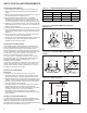
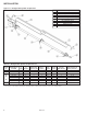
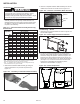
Figure 7.1 - U-Tube System Components
Tube Double-Tube Double-Tube Turbulator Stocking Kit
Length Available Burner 5' 10' 10' Hangers with Hangers Tube Reector Bafe Option Requires the
(ft.) Input MBH Tubes Tubes Reectors Reinforcing Bar (regular) Clamps End Cap U-Tube Sections ➂ Following Tube Kits ➁
20 50, 60, 75 - 2 2 2 - 4 4 1 4 A + U-Tube
30 50, 60, 75, 100 2 2 4 2 1 6 4 1 4 N/A
40 60, 75, 100, 125 - 4 4 2 1 6 4 1 4 A + D + U-Tube
50 100, 125, 150, 175, 200 2 4 ➀ 6 2 2 8 ➀ 4 1 4 N/A
60 125 - 1-Stage Only - 6 6 2 2 8 4 1 4 A + D + D + U-Tube
60 150, 175, 200 - 6 ➀ 6 2 2 8 ➀ 4 1 4 B + D + U-Tube
70 175, 200 2 6 ➀ 8 2 3 10 ➀ 4 1 4 N/A
➀ Tube systems for input ratings of 150MBH and higher utilize a 409 Aluminized Stainless Steel First tube section with stainless steel tube clamps.
➁ Tube systems can be ordered as either Modular (complete system) or Stocking Kits (combination of kits to form complete system).
➂ Forinstallationswhere4bafesareneedonstraighttubesetups,U-tubeinstallationswillonlyrequire3bafes.
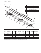
Table 7.1 - U-Tube System Component List
INSTALLATION
Ref # Part Description
1 Burner
2 Burner Support Bracket (Qty. 4)
3 Tube Clamp
4 DoubleTube&ReectorHangerw/ReinforcingBar
5 Radiant Tube
6 DoubleTube&ReectorHanger
7 U-Tube
8 Reector
9 ReectorEndCap
10 TurbulatorBafe