
IPT Installation Manual


8
9-511.4
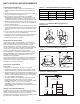
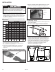
For steps 1-8 of this section, please refer to Figures 8.1 and 9.1
1. Locate and install tube and reflector system hanging chains
(200 lb. minimum working load) as shown, following spacing
indicated in Table 8.1 or 9.1.
2. Fasten tube and reflector hangers to the hanging chains
installed in the previous step using ¼" diameter S-Hooks (70
lb. minimum working load). The hangers must be positioned
so that the tube system to be installed will be in the horizontal
plane and level. Refer to Figures 8.1 and 9.1 for chain
location on tube systems mounted at a 45° angle. Also note
that the first and last hangers are to be the type with
reinforcing bar. Do not close ends until the tube system
installed in subsequent steps is confirmed to be level.
3. Identify the first burner tube and first and second tube clamps
as follows:
All chains to hang from
overhead structure designed
to support system weight.
TUBE SYSTEM
LENGTH
INSTALLATION
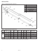
Figure 8.1 - Straight Tube System Suspension
Ref # Part Description
1 Burner (Installed In Later Steps)
2 TurbulatorBafe
3 Chain & “S” Hooks
4 Radiant Tube
5 Tube&ReectorHangerw/ReinforcingBar
6 Tube Clamp
7 Self-Tapping Sheet Metal Screws
8 Tube&ReectorHanger
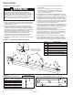
Figure 8.2 - Tube Ends (Dimensions in inches)
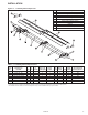
Tube System Number of Minimum "A" "B" "C"
Length (ft) Chains Chain Length ➀ ➁ ➂
20 3 18"
30 4 18"
40 5 18"
50 6 18"
60 7 24"
70 8 24"
➀"A"Dimensionisspacingfromthetubesystemendstotherstandlasthangers.
➁ "B" Dimension is spacing between hangers for tubes between "C" dimensions.
➂"C"Dimensionisspacingbetweenthersttwohangersandthelast2hangers.
6"
N/A
Chain to Chain
Spacing Dimensions
Table 8.1 -
Straight Tube Chain Spacing
9' 8"
9' 4"
Unit Mounting – Tube System
WARNING
To prevent tube sections from separating during unit
operation, tube clamps must be centered over the joints of
adjoining tube sections and tightened to 50 ft. - lb. and the
clamp fastened to the tubes using (2) self-tapping screws.
Failure to do so may result in separation of tube sections
which could fall and result in death or serious injury.
• For units under 150,000 Btu/hr, all tubes and clamps
are the same.
• For units 150,000 Btu/hr and over, the first tube is
shinier than the other tubes and is stenciled with the
words “First Tube”. The first two tube clamps have a
shiny, mirror-like appearance.
4. Loosely slide the second tube clamp approximately 6" past
the swaged end (see Figure 8.2 for identification of tube ends).
5. Starting from the end of the tube system where the burner will
be installed (done in later steps), slide the first burner tube
through the first and second tube hangers. The non-swaged
end is to go through the first tube hanger and the swaged end
is to go through the second tube hanger. Position the tube so
the welded seam is directed toward the floor.
6. Loosely slide the next tube clamp over the swaged end of the
next tube and slide the non-swaged end over the swaged end
of the preceding tube, ensuring that the welded seam on the
tube is directed toward the floor. The other end is to be
inserted through the following tube hanger.
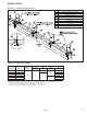
7. Center the tube clamp on the preceding tube over the joint of
the two tubes as shown in Figures 8.1 or 9.1 and tighten the
tube clamp bolts to 50 ft.-lb. Secure the tube clamp to both
tubes using (2) self-tapping sheet metal screws.
8. Repeat steps 6 and 7 until all tube sections are installed.
9. Verify that the tube system is level. If the tube is not level,
adjust the position of the hanger on the hanging chain. Once
level, crimp the ends of the S-hooks on the hangers closed.