
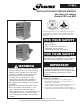
Install Instructions

6-580.5
2
Special Precautions
THE INSTALLATION AND MAINTENANCE INSTRUCTIONS
IN THIS MANUAL MUST BE FOLLOWED TO PROVIDE
SAFE, EFFICIENT AND TROUBLE-FREE OPERATION.
IN ADDITION, PARTICULAR CARE MUST BE EXERCISED
REGARDING THE SPECIAL PRECAUTIONS LISTED BELOW.
FAILURE TO PROPERLY ADDRESS THESE CRITICAL
AREAS COULD RESULT IN PROPERTY DAMAGE OR LOSS,
PERSONAL INJURY, OR DEATH. THESE INSTRUCTIONS
ARE SUBJECT TO ANY MORE RESTRICTIVE LOCAL OR
NATIONAL CODES.
HAZARD INTENSITY LEVELS
1. DANGER: Indicates an imminently hazardous situation
which, if not avoided, WILL result in death or serious injury.
2. WARNING: Indicates a potentially hazardous situation which,
if not avoided, COULD result in death or serious injury.
3. CAUTION: Indicates a potentially hazardous situation which,
if not avoided, MAY result in minor or moderate injury.
4. IMPORTANT: Indicates a situation which, if not avoided,
MAY result in a potential safety concern.
SPECIAL PRECAUTIONS / TABLE OF CONTENTS
IMPORTANT
1. To prevent premature heat exchanger failure, do not
locate ANY gas-fired appliances in areas where corrosive
vapors (i.e. chlorinated, halogenated or acid) are present
in the atmosphere.
2. Do not attempt to attach ductwork of any kind to propeller
models.
3. To prevent premature heat exchanger failure, observe
heat exchanger tubes. If the bottom of the tubes become
red while blower and furnace are in operation, check
to be sure the blower has been set to the proper rpm
for the application. Refer to page 9 for Blower Adjustments.
4. Start-up and adjustment procedures should be performed
by a qualified service agency.
5. To check most of the Possible Remedies in the trouble-
shooting guide listed in Table 21.1, refer to the applicable
sections of the manual.
6. To prevent premature heat exchanger failure, the input to
the appliance, as indicated on the serial plate, must not
exceed the rated input by more than 5%.
Table of Contents
Inspection on Arrival................................. 1
Special Precautions ................................. 2
SI (Metric) Conversion Factors ........................ 3
Unit Location ...................................... 3
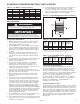
Combustible Material and Service Clearances ......... 3
Combustion Air Requirements ..................... 3
Unit Lifting and Unit Mounting...................... 4
Installation ........................................ 4
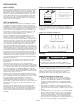
Venting ....................................... 4
Gas Connections................................ 7
Electrical Connections............................ 8
Duct Installation................................. 8
Blower Adjustment .............................8-9
Start-Up Procedure ................................ 10
Pilot Burner Adjustment.......................... 10
Main Burner Adjustment ......................... 10
Control Operating Sequence...................... 11
Options .......................................... 12
General Performance Data ....................... 13-15
Performance Data Hoods/Nozzles .................. 16-17
Dimensions Unit ................................ 18-19
Maintenance...................................... 20
Service & Troubleshooting ........................ 21-22
Model Nomenclature/Serial Plate....................22-23
Commercial Warranty........................ Back Page
cAUTION
1. Purging of air from gas supply line should be performed
as described in ANSI Z223.1 - latest edition “National Fuel
Gas Code”, or in Canada in CAN/CGA-B149 codes.
2. Do not attempt to reuse any mechanical or electronic
ignition controllers which has been wet. Replace defective
controller.
3. Ensure that the supply voltage to the appliance, as
indicated on the serial plate, is not 5% less than the rated
voltage.
dANGER
Appliances must not be installed where they may be exposed
to a potentially explosive or flammable atmosphere.
WARNING
1. Gas fired heating equipment must be vented - do not
operate unvented.
2. A built-in power exhauster is provided - additional external
power exhausters are not required or permitted.
3. All field gas piping must be pressure/leak tested prior to
operation. Never use an open flame. Use a soap solution or
equivalent for testing.
4. Gas pressure to appliance controls must never exceed 14"
W.C. (1/2 psi).
5. Disconnect power supply before making wiring connections
to prevent electrical shock and equipment damage.
6. All appliances must be wired strictly in accordance with
wiring diagram furnished with the appliance. Any wiring
different from the wiring diagram could result in a hazard
to persons and property.
7. Any original factory wiring that requires replacement
must be replaced with wiring material having a
temperature rating of at least 105°C.
8. When servicing or repairing this equipment, use only
factory-approved service replacement parts. A complete
replacement parts list may be obtained by contacting
Modine Manufacturing Company. Refer to the rating
plate on the appliance for complete appliance model
number, serial number, and company address. Any
substitution of parts or controls not approved by the
factory will be at the owners risk.
9. To reduce the opportunity for condensation, the minimum
sea level input to the appliance, as indicated on the
serial plate, must not be less than 5% below the rated
input, or 5% below the minimum rated input of dual rated
units.
10. Ensure that the supply voltage to the appliance, as
indicated on the serial plate, is not 5% greater than the
rated voltage.