
Install Instructions

6-580.5
Location Recommendations
1. When locating the furnace, consider general space and
heating requirements, availability of gas and electrical
supply, and proximity to vent locations.
2. Avoid installing units in extremely drafty locations. Drafts
can cause burner flames to impinge on heat exchangers
which shortens life. Maintain separation between units so
discharge from one unit will not be directed into the inlet
of another.
3. Be sure the structural support at the unit location site is
adequate to support the weight of the unit. For proper
operation the unit must be installed in a level horizontal
position.
4. Do not install units in locations where the flue products can
be drawn into the adjacent building openings such as
windows, fresh air intakes, etc.
5. Be sure that the minimum clearances to combustible
materials and recommended service clearances are
maintained. Units are designed for installation on non-
combustible surfaces with the minimum clearances shown
in Figure 3.1 and Tables 3.2 and 3.3.
6. Units exposed to inlet air temperatures of 40°F or less,
may experience condensation, therefore, provisions should
be made for disposal of condensate.
7. When locating units, it is important to consider that the
exhaust vent piping must be connected to the outside
atmosphere.
8. In garages or other sections of aircraft hangars such as
offices and shops that communicate with areas used for
servicing or storage, keep the bottom of the unit at least
7 feet above the floor unless the unit is properly guarded
to provide user protection from moving parts. In parking
garages, the unit must be installed in accordance with the
standard for parking structures ANSI/NFPA 88A, and in
repair garages the standard for repair garages NFPA #88B.
In Canada, installation of heaters in airplane hangars must
be in accordance with the requirements of the enforcing
authority, and in public garages in accordance with the
current CAN/CGA-B149 codes.
9. Do not install units in locations where gas ignition system
is exposed to water spray, rain, or dripping water.
10. Do not install units below 7 feet, measured from the bottom
of the unit to the floor, unless properly guarded to provide
protection from moving parts.
11. In aircraft hangars, keep the bottom of the unit at least 10
feet from the highest surface of the wings or engine
enclosure of the highest aircraft housed in the hangar
and in accordance with the requirements of the enforcing
authority and/or NFPA No. 409 - Latest Edition.
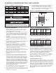
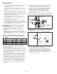
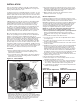
Figure 3.1 - Combustible Material and Service Clearances
Combustion Air Requirements
Units installed in tightly sealed buildings or confined spaces
must be provided with two permanent openings, one near the
top of the confined space and one near the bottom. Each
opening should have a free area of not less than one square
inch per 1,000 BTU per hour of the total input rating off all units
in the enclosure, freely communicating with interior areas
having, in turn adequate infiltration from the outside.
For further details on supplying combustion air to a confined
(tightly sealed) space or unconfined space, see the National
Fuel Gas Code ANSI Z223.1 of CAN/CGA B149.1 or .2
Installation Code, latest edition.
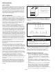
Sound and Vibration Levels
All standard mechanical equipment generates some sound and
vibration that may require attenuation. Libraries, private offices
and hospital facilities will require more attenuation, and in such
cases, an acoustical consultant may be retained to assist in the
application. Locating the equipment away from the critical area
is desirable within ducting limitations. Generally, a unit should
be located within 15 feet of a primary support beam. Smaller
deflections typically result in reduced vibration and noise
transmission.
3
SI (METRIC) CONVERSION FACTORS / UNIT LOCATION
dANGER
Appliances must not be installed where they may be exposed
to a potentially explosive or flammable atmosphere.
IMPORTANT
To prevent premature heat exchanger failure, do not locate
ANY gas-fired appliances in areas where corrosive vapors (i.e.
chlorinated, halogenated or acid) are present in the atmosphere.
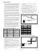
To Convert Multiply By To Obtain
"W.C. 0.24 kPa
psig 6.893 kPa
°F (°F-32) x 0.555 °C
inches 25.4 mm
feet 0.305 meters
CFM 0.028 m
3
/min
To Convert Multiply By To Obtain
CFH 1.699 m
3
/min
Btu/ft
3
0.0374 mJ/m
3
pound 0.453 kg
Btu/hr 0.000293 kW/hr
gallons 3.785 liters
psig 27.7 "W.C.
A
D
B
C
Access
Side
Table 3.2 - Combustible Material Clearances ➀
➀ Provide sufficient room around the heater to allow for proper
combustion and operation of fan. Free area around the heater must
not be less than 1-1/2 times the discharge area of the unit.
Access Non-Access Top of Power
Model Side Side Top Bottom Exhauster
Size (A) (B) (C) (D) (Not shown)
150-175 1 1 4 12 2
200-400 1 1 5 12 3
Table 3.3 - Recommended Service Clearances
Access Non-Access Top of Power
Model Side Side Top Bottom Exhauster
Size (A) (B) (C) (D) (Not shown)
150-175 18 18 6 22 1
200-400 18 18 6 25 1
Table 3.1 - SI (Metric) Conversion Factors
UNIT LOCATION