
Install Instructions

6-580.5
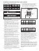
A pipe hanger adapter kit, shown in Figure 4.2 is available as
an accessory. One kit consists of two drilled 3/4” IPS pipe caps
and two 3/8 - 13 x 1-3/4” capscrews to facilitate threaded pipe
suspension.
Venting
NOTE: A vent is the vertical passageway used to convey
flue gases from the unit or the vent connector to the outside
atmosphere. A vent connector is the pipe which connects the
unit to a vent or chimney. Vent connectors serving Category
I appliances shall not be connected into any portion of
mechanical draft systems operating under positive pressure.
General Venting Air Instructions
1. Installation of venting must conform with local building
codes, or in the absence of local codes, with the National
Fuel Gas Code, ANSI Z223.1 (NFPA 54) - Latest Edition.
In Canada, installation must be in accordance with CAN/
CGA-B149.1 for natural gas units and CAN/CGA-B149.2 for
propane units.
2. All vertically vented units are Category I. All horizontally
vented units are category III. The installation must conform
to the requirements from Table 5.1 in addition to those listed
below.
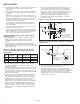
3. From Table 18.9 or 19.1, select the size of vent pipe that fits
the flue outlet for the unit. Do not use a vent pipe smaller
than the size of the outlet or vent transition of the appliance.
The pipe should be suitable corrosion resistant material.
Follow the National Fuel Gas Code for minimum thickness
and composition of vent material. The minimum thickness for
connectors varies depending on the pipe diameter.
4
INSTALLATION
UNIT LIFTING
All units are shipped fully boxed. Larger units are also supplied
with skid supports on the bottom of the box. The larger units
may be lifted from the bottom by means of a fork lift or other
lifting device only if the shipping support skids are left in place
and the forks support the whole depth of the unit. If the unit
must be lifted from the bottom for final installation without the
carton in place, be sure to properly support the unit over its
entire length and width to prevent damage. When lifting units,
make sure the load is balanced.
UNIT SUSPENSION
Be sure the method of unit suspension is adequate to support
the weight of the unit (see Weights for base unit and factory
installed option weights). For proper operation, the unit must be
installed in a level horizontal position. Combustible material and
service clearances as specified in Figure 3.1 and Tables 3.2
and 3.3 must be strictly maintained. To assure that flames are
directed into the center of the heat exchanger tubes, the unit
must be level in a horizontal position. Use a spirit level to
ensure that the unit is suspended correctly.
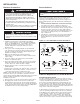
The most common method of suspending Modine gas unit
heaters is to utilize 3/8” threaded rod. On each piece of
threaded rod used, screw a nut a distance of about one inch
onto the end of the threaded rods that will be screwed into the
unit heater. Then place a washer over the end of the threaded
rod and screw the threaded rod into the unit heater weld nuts
on the top of the heater at least 5 turns, and no more than 10
turns. Tighten the nut first installed onto the threaded rod to
prevent the rod from turning. Drill holes into a steel channel or
angle iron at the same centerline dimensions as the heater that
is being installed. The steel channels or angle iron pieces need
to span and be fastened to appropriate structural members. Cut
the threaded rods to the preferred length, place them through
the holes in the steel channel or angle iron and secure with
washers and lock nuts or lock washers and nuts. A double nut
arrangement can be used here instead of at the unit heater (a
double nut can be used both places but is not necessary). Do
not install standard unit heaters above the maximum mounting
height shown in Table 13.1.
On all propeller units, except sizes 350 and 400, two tapped
holes (3/8-16) are located in the top of the unit to receive
threaded rods.
Units with two point suspension, sizes 150 through 300,
incorporate a level hanging feature. Depending on what options
and accessories are being used, the heater may not hang level
as received from the factory. Do not hang heaters with deflector
hoods until referring to the “Installation Manual for Deflector
Hoods” and making the recommended preliminary adjustments
on the heater. These preliminary adjustments need to be made
with the heater resting on the floor.
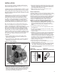
Propeller sizes 150 through 300 units without deflector hoods
that do not hang level after being installed, can be corrected in
place. Simply remove both outer side panels (screws to remove
are on back flange of side panel) and you will see the
(adjustable) mounting brackets (Fig. 4.1). Loosen the set
screws holding the mounting brackets in place and using a
rubber mallet or similar, tap the heater into a position where the
unit hangs level. Re-tighten set screws and replace the outer
side panels.
Propeller sizes 350 and 400 have four mounting holes. On
all blower units, except the 350 and 400, two tapped holes
are provided in the top of the unit and two holes in the blower
support bracket. The 350 and 400 have four tapped holes in
the top of the unit and two in the blower support bracket for
mounting.
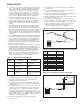
Figure 4.2 - Suspension Methods
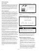
1. Remove outer side panels.
2. “Set screws” - loosen and
position bracket where needed
– then tighten set screws.
3. Re-attach outer side panels.
Figure 4.1 - Adjustable Mounting Brackets - To Adjust:
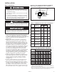
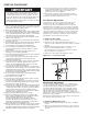
WARNING
1. Gas fired heating equipment must be vented - do not
operate unvented.
2. A built-in power exhauster is provided - additional
external power exhausters are not required or permitted.