
Install Instructions

6-580.5
5
4. For Category I vent systems limit length of horizontal runs to
75% of vertical height. Install with a minimum upward slope
from unit of 1/4 inch per foot and suspend securely from
overhead structure at points no greater than 3 feet apart.
For best venting, put vertical vent as close to the unit as
possible. A minimum of 12" straight pipe is recommended
from the power exhauster outlet before turns in the vent
system. Fasten individual lengths of vent together with at
least three corrosion-resistant sheet-metal screws.
5. It is recommended that vent pipes be fitted with a tee with
a drip leg and a clean out cap to prevent any moisture in the
vent pipe from entering the unit. The drip leg should be
inspected and cleaned out periodically during the heating
season.
6. The National Fuel Gas Code requires a minimum clearance
of 6 inches from combustible materials for single wall vent
pipe. The minimum distance from combustible materials is
based on the combustible material surface not exceeding
160°F. Clearance from the vent pipe (or the top of the unit)
may be required to be greater than 6 inches if heat damage
other than fire (such as material distortion or discoloration)
could result.
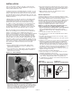
7. Avoid venting through unheated space. When venting does
pass through an unheated space, insulate runs greater than
5 feet to minimize condensation. Inspect for leakage prior to
insulating and use insulation that is noncombustible with a
rating of not less than 350°F. Install a tee fitting at the low
point of the vent system and provide a drip leg with a clean
out cap as shown in Figure 5.1.
8. When the vent passes through a combustible wall or floor, a
metal thimble 4 inches greater than the vent diameter is
necessary. If there is 6 feet or more of vent pipe in the open
space between the appliance and where the vent pipe
passes through the wall or floor, the thimble need only be
2 inches greater than the diameter of the vent pipe. If a
thimble is not used, all combustible material must be cut
away to provide 6 inches of clearance. Any material used
to close the opening must be noncombustible.
9. Do NOT use dampers or other devices in the vent pipes.
10. Precautions must be taken to prevent degradation of
building materials by flue products.
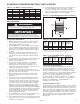
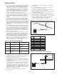
11. For category I vent systems the outlet of the vent should
extend as shown in Figure 5.1 and Table 5.2 if the following
conditions are met:
Vent diameter is less than 12 inches, vent is of double wall
construction and is a listed product, and the vent does not
terminate within 2' of a vertical wall or similar obstruction.
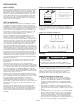
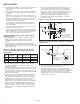
For vents that have a diameter of 12 inches or larger,
constructed of single wall, or terminate within 2' of a vertical
wall or similar obstruction, the vent pipe shall extend at least
2' higher than any portion of a building within a horizontal
distance of 10' (refer to Figure 5.2).
12. Use a listed vent terminal to reduce downdrafts and
moisture in vent.
13. For instructions on common venting refer to the National
Fuel Gas Code.
14. The vent must terminate no less than 5' above the vent
connector for category I vent systems.
15. A unit located within an unoccupied attic or concealed space
shall not be vented with single wall vent pipe.
16. Single wall vent pipe must not pass through any attic, inside
wall, concealed space, or floor.
17. Do NOT vent this appliance into a masonry chimney.
18. When condensation may be a problem, the venting system
shall not terminate over public walkways or over an area
where condensation or vapor could create a nuisance or
hazard or could be detrimental to the operation of
regulator/relief openings or other equipment.
INSTALLATION
T
able 5.2 - Minimum Height from Roof to Vent Discharge
Rise Roof Pitch Min Height
X (in) H (ft)*
0-6 Flat to 6/12 1.00
6-7 6/12 to 7/12 1.25
7-8 7/12 to 8/12 1.50
8-9 8/12 to 9/12 2.00
9-10 9/12 to 10/12 2.50
10-11 10/12 to 11/12 3.25
11-12 11/12 to 12/12 4.00
12-14 12/12 to 14/12 5.00
14-16 14/12 to 16/12 6.00
16-18 16/12 to 18/12 7.00
18-20 18/12 to 20/12 7.50
20-21 20/12 to 21/12 8.00
* Size according to expected snow depth.
Table 5.1 - ANSI Venting Requirements
Appliance Venting
Category Description Requirements
I Negative vent pressure Follow standard venting
Non-condensing requirements.
II Negative vent pressure Condensate must be
Condensing drained.
III Positive vent pressure Vent must be gastight.
Non-condensing
IV Positive vent pressure Vent must be liquid and
Condensing gastight. Condensate must
be drained.
Slope 1/4" to
The Foot
Unit
Drip Leg with
Cleanout Cap
Use Thimble
Through Ceiling
H
1'0"
1/4"
x
12
Roof Pitch is x/12
Listed
T e rminal
Roof
Flashing
Figure 5.1 - Unit Venting Category I (pitched roof)
1/4"
Slope 1/4" to
The Foot
*Size according to
expected snow depth
Drip Leg with
Cleanout Cap
Use Thimble
Through Ceiling
Roof Flashing
Listed
Terminal
2� Min.
2�*
Min.
To wall or adjoining building
10"
Unit
Figure 5.2 - Unit Venting Category (obstructed)