
Install Instructions

6-580.5
1. Installation of wiring must conform with local building
codes, or in the absence of local codes, with the National
Electric Code ANSI/NFPA 70 - Latest Edition. Unit must be
electri cally grounded in conformance to this code. In
Canada, wiring must comply with CSA C22.1, Part 1,
Electrical Code.
2. Two copies of the unit wiring diagram are provided with
each unit. One is located in the electrical junction box and
the other is suppled in the literature packet. Refer to this
diagram for all wiring connections.
3. Make sure all multi-voltage components (motors,
transform ers, etc.) are wired in accordance with the power
supply voltage.
4. The power supply to the unit must be protected with a
fused or circuit breaker switch.
5. The power supply must be within 10 percent of the voltage
rating and each phase must be balanced within 2 percent
of each other. If not, advise the utility company.
6. External electrical service connections that must be
installed include:
a. Supply power connection (120, 208, 240, 480, or 600 volts).
b. Thermostats, summer/winter switches, or other accessory
control devices that may be supplied (24 volts).
NOTE: Certain units will require the use of a field step-down
transformer. Refer to the serial plate to determine the unit
supply voltage required. Additional information may be found in
Tables 13.2 and 13.3 and in the step down transformer
installation instructions.
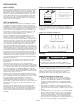
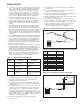
7. Refer to Figure 12.1 for the electrical junction box locations.
8. All supply power electrical connections are made in the
electrical junction box of the unit. The low voltage (thermostat
and accessory control devices) can be wired to the terminals
on the electrical junction box. Refer to the wiring diagram for
the terminal location of all low voltage wiring.
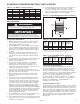
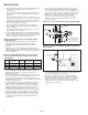
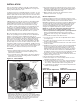
Duct Installation
When installing the heater, always follow good duct design
practices for even distribution of the air across the heat
exchanger. Recommended layouts are shown in Figure 8.1.
When installing blower units with ductwork the following must
be done.
1. Provide uniform air distribution over the heat exchanger.
Use turning vanes where required. See Figure 8.1.
2. Provide removable access panels in the ductwork on the
downstream side of the unit heater. These openings should
be large enough to view smoke or reflect light inside the
casing to indicate leaks in the heat exchanger and to check
for hot spots on exchanger due to poor air distribution or
lack of sufficient air.
3. If ductwork is connected to the rear of the unit use Modine
blower enclosure kit or if using field designed enclosure
maintain dimensions of blower enclosure as shown on
page 19.
Additional Requirements for Blower Model BDP
Determining Blower Speed
The drive assembly and motor on all blower units are factory
assembled and adjusted for operation under average conditions
of air flow and without any external static pressure. The
motor sheave should be adjusted as required when the unit
is to be operated at other than average air flows and/or with
external static pressures. Adjustment must always be within the
performance range shown on page 14 and the temperature rise
range shown on the unit’s rating plate.
To determine the proper blower speed and motor sheave turns
open, the operating conditions must be known. For example, a
model BDP350 unit, operating with no external static pressure,
(e.g. no ductwork, nozzles, etc.) is to deliver an air volume
of 6481 cfm (cfm = cubic feet per minute). This requires the
unit be supplied with a 5 hp motor, a -207 drive, and the drive
sheave set at 2.5 turns open to achieve a blower speed of 960
A
BAFFLE
B
12" MIN.
B
3" MAX.
TURNING
VANES
3" MIN.
A
A
3" MIN.
12"
MIN.
3" MAX.
TURNING
VANES
12"
B
BAFFLE
A
B
12"
MIN.
BAFFLE
TURNING
VANES
SIDE VIEW
Dimension “B” Should Never Be Less than 1/2 of “A”
SIDE VIEW
SIDE VIEW TOP VIEW
8
INSTALLATION
IMPORTANT
Do not attempt to attach ductwork of any kind to propeller
models.
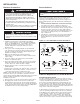
Electrical Connections
WARNING
1. Disconnect power supply before making wiring connections
to prevent electrical shock and equipment damage.
2. All appliances must be wired strictly in accordance with
wiring diagram furnished with the appliance. Any wiring
different from the wiring diagram could result in a hazard to
persons and property.
3. Any original factory wiring that requires replacement must
be replaced with wiring material having a temperature rating
of at least 105°C.
4. Ensure that the supply voltage to the appliance, as indicated
on the serial plate, is not 5% greater than rated voltage.
cAUTION
1. Ensure that the supply voltage to the appliance, as
indicated on the serial plate, is not 5% less than the rated
voltage.
Figure 8.1 - Recommended Ductwork Installations