
installation manual


10
6-580.5
1. Turn off power to the unit at the disconnect switch. Check that
fuses or circuit breakers are in place and sized correctly. Turn
all hand gas valves to the “OFF” position.
2. Remove electrical junction box cover.
3. Check that the supply voltage matches the unit supply voltage
listed on the Model Identification plate. Verify that all wiring is
secure and properly protected. Trace circuits to insure that the
unit has been wired according to the wiring diagram.
4. Check to insure that the venting system is installed correctly
and free from obstructions.
5. Check to see that there are no obstructions to the intake and
discharge of the unit.
6. For blower units, check the belt tension and sheave alignment.
Refer to Blower Adjustments for proper belt tension.
7. Check bearings for proper lubrication (if applicable).
8. Check to make sure that all filters are in place and that
they are installed properly according to direction of air flow
(if applicable).
9. Perform a visual inspection of the unit to make sure no
damage has occurred during installation.
10. Check that all horizontal deflector blades are open a minimum
of 30° as measured from vertical.
11. Turn on power to the unit at the disconnect switch. Check to
insure that the voltage between electrical junction box
terminals T1 and G is 24V.
12. Check the thermostat, ignition control, gas valve, and supply
fan blower motor for electrical operation. If these do not
function, recheck the wiring diagram. Check to insure that
none of the Control Options have tripped.
13. Check the blower wheel for proper direction of rotation when
compared to the air flow direction arrow on the blower housing
(if applicable). Blower wheel rotation, not air movement, must
be checked as some air will be delivered through the unit with
the blower wheel running backwards.
14. For blower units, check the blower speed (rpm). Refer to
Blower Adjustments for modification.
15. Check the motor speed (rpm).
16. Check the motor voltage. On three phase systems, check to
make sure all legs are in balance.
17. Check the motor amp draw to make sure it does not exceed
the motor nameplate rating. On three phase systems, check
all legs to insure system is balanced.
18. Recheck the gas supply pressure at the field installed manual
shut-off valve. The minimum inlet pressure should be 6" W.C.
on natural gas and 11" W.C. on propane gas. The maximum
inlet pressure for either gas is 14" W.C. If inlet pressure
exceeds 14" W.C., a gas pressure regulator must be added
upstream of the combination gas valve.
19. Open the field installed manual gas shut-off valve.
20. Open the manual main gas valve on the combination gas
valve. Call for heat with the thermostat and allow the pilot to
light for intermittent pilot ignition. If the pilot does
not light, purge the pilot line. If air purging is required,
disconnect the pilot line at outlet of pilot valve. In no case
should line be purged into heat exchanger. Check the pilot
flame length (See Pilot Flame Adjustment).
21. Once the pilot has been established, check to make sure that
the main gas valve opens. Check the manifold gas pressure
(See Main Gas Adjustment) and flame length (See Air Shutter
Adjustment) while the supply fan blower is operating.
22. Check to insure that gas controls sequence properly (See
Control Operating Sequence). Verify if the unit has any
additional control devices and set according to the
instructions in the Control Options.
23. Once proper operation of the unit has been verified,
remove any jumper wires that were required for testing.
24. Replace the electrical junction box cover.
Pilot Burner Adjustment
The pilot burner is orificed to burn properly with an inlet
pressure of 6-7” W.C. on natural gas and 11-14” W.C.
on propane gas, but final adjustment must be made after
installation. If the pilot flame is too long or large, it is possible
that it may cause soot and/or impinge on the heat exchanger
causing failure. If the pilot flame is shorter than shown, it may
cause poor ignition and result in the controls not opening the
combination gas control. A short flame can be caused by a
dirty pilot orifice. Pilot flame condition should be observed
periodically to assure trouble-free operation.
To Adjust the Pilot Flame
1. Create a call for heat from the thermostat.
2. Remove the cap from the pilot adjustment screw. For
location, see the combination gas control literature supplied
with unit.
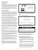
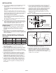
3. Adjust the pilot length by turning the screw in or out to
achieve a soft steady flame 3/4” to 1” long and
encompassing 3/8”-1/2” of the tip of the thermocouple or
flame sensing rod (see Figure 10.1).
4. Replace the cap from the pilot adjustment screw.
Main Burner Adjustment
The gas pressure regulator (integral to the combination gas
control) is adjusted at the factory for average gas conditions.
It is important that gas be supplied to the unit heater in
accordance with the input rating on the serial plate. Actual
input should be checked and necessary adjustments made
after the unit heater is installed. Over-firing, a result of too
high an input, reduces the life of the appliance and increases
maintenance. Under no circumstances should the input exceed
that shown on the serial plate.
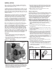
Measuring the manifold pressure is done at the outlet pressure
tap of the gas valve (see Figure 11.1).
To Adjust the Manifold Pressure
1. Move the field installed manual shut-off valve to the “OFF”
position.
2. Remove the 1/8" pipe plug in the pipe tee or gas valve and
attach a water manometer of “U” tube type which is at least
12" high.
10
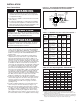
START-UP PROCEDURE
IMPORTANT
1. To prevent premature heat exchanger failure, observe
heat exchanger tubes. If the bottom of the tubes become
red while blower and furnace are in operation, check to
be sure the blower has been set to the proper rpm for the
application. Refer to page 9 for Blower Adjustments.
2. Start-up and adjustment procedures should be performed
by a qualified service agency.
3/4" to 1"
Figure 10.1 - Correct Pilot Flame