
installation manual


6-580.5
19. In cold ambient conditions, such as Canada, the following
items are recommended for proper operation and
equipment life:
· The vent pipe must not pass through an unheated space
or interior part of an open chimney unless the vent pipe is
insulated.
· Where the vent pipe may be exposed to extreme cold, or
come into contact with snow or ice, the entire vent must be
insulated or double wall (includes outdoors). It is preferred
that the double wall vent is one continuous piece but a
joint is allowed outside the building.
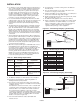
· The vent terminal must extend 12 inches beyond the
exterior surface of an exterior wall and be supported as
shown in Figure 6.1.
· The heater system shall be checked at least once a year
by a qualified service technician.
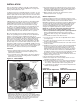
20. If left hand (facing front of heater with air blowing in face)
power exhauster discharge is desired, the power exhauster
may be rotated 180°. To do this, remove screws in vent
collar, rotate power exhauster, replace screws.
Additional Requirements for Horizontally Vented
Category III units.
1. Seal the joints with a metallic tape or silastic suitable for
temperatures up to 350°F. (3M tapes 433 or 363 are
acceptable.) Wrap the tape two full turns around the
vent pipe.
2. Refer to Table 6.1 for total minimum and maximum vent
lengths making the vent system as straight as possible. The
equivalent length of a 90° elbow is 6 feet for 5" diameter and
7 feet for 6" diameter.
3. The vent terminal must be a Gary Steel 1092, Tjernlund
VH1, Starkap, Selkirk, or Constant Air -Flo 2433 style
terminal or equivalent.
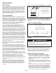
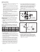
4. If a Gary Steel 1092 vent terminal or equivalent is used, the
vent can extend 6 inches beyond the exterior surface of an
exterior wall rather than 12 inches as shown in Figure 6.2.
Precautions must be taken to prevent degradation of building
materials by flue products.
5. If a Tjernlund VH1 or equivalent vent terminal is used the
vent may be flush with the exterior surface of an exterior
wall. Precautions must be taken to prevent degradation of
building materials by flue products. Where the terminal is
not available in the appropriate size for the unit to be
installed, use a transition and the next larger size terminal.
6. If a Constant Air-Flo, Starkap, Selkirk, or equivalent vent
terminal is used the vent must extend 12 inches beyond
the exterior surface of an exterior wall. Precautions must
be taken to prevent degradation of building materials by
flue products.
7. The vent system shall terminate at least 3 feet above any
forced air inlet (except direct vent units) located within
10 feet, and at least 4 feet below, 4 feet horizontally from, or
1 foot above any door, window, or gravity air inlet into any
building. The bottom of the vent terminal shall be located
above the snow line or at least 1 foot above grade;
whichever is greater. When located adjacent to public
walkways the vent system shall terminate not less than
7 feet above grade.
8. The venting system must be exclusive to a single unit, and
no other unit is allowed to be vented into it.
9. Horizontally vented units must use single wall vent pipe
although one continuous section of double wall vent pipe
may be used with the vent system. Under no circumstances
should two sections of double wall vent pipe be joined
together within one vent system due to the inability to verify
complete seal of inner pipes.
6
INSTALLATION
METAL
SLEEVE
FIBER GLASS
INSULATION
MIN. 2"
2" MIN.
VENT TERMINATION
SUPPORT BRACKET
(where required)
(Make from 1" x 1" steel angle)
9"
9"
45
1"
METAL
SLEEVE
2" MIN.
VENT PIPE
DIAMETER
METAL FACE
PLATE
1"
12" min
TEE WITH DRIP LEG
AND CLEANOUT CAP
AT LOW POINT OF
VENT SYSTEM
POWER EXHAUSTER
PITCH VENT PIPE DOWNWARD
FROM UNIT 1/4" PER FOOT
12"
Min.
GARY STEEL
MODEL 1092 TERMINAL
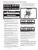
Figure 6.1 - Vent Construction Through Combustible Walls
Figure 6.2 - Horizontal Venting - Breidert or Gary Steel
Vent Terminal
Model Vent Transition Vent Pipe Minimum Maximum
Size Included Diameter Eqv Length Eqv Length
150, 175 4" to 5" 5" 2' 60'
200 6" to 5" 5" 2' 60'
250- 400 Not Required 6" 2' 70'
Table 6.1 - Vent Pipe Diameters, Transitions, and
Total Equivalent Vent Pipe Lengths for Horizontal
Vent Systems