
Specification

22
6-189.9
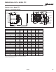
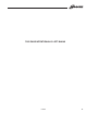
DIMENSIONAL DATA - MODEL BDP
W
X
F
C
CC
G
DD
J
M (APPROX.)
L (MIN. DISTANCE TO WALL)
N
S
O
K
EE
5
CC
DD
J
P
Q x V
R x T
/
8"
7
4
/
16"
9
5
/
4"
3
/16"
9
FILTER RACK
(OPTIONAL)
LOWER
ENCLOSRE
(OPTIONAL)
A
D (OPENING)
E
AA
K
L (MIN. DISTANCE TO WALL)
G
➀
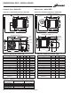
For some models, this is the dimension of the vent transition outlet supplied.
➁
BDP 150 thru BDP 300 — 4 holes (2 on blower and 2 on unit). BDP 350 and BDP 400 —-6 holes (2 on blower
and 4 on unit). (Listed is the hole diameter and threads per inch to accept threaded rod).
➂
This is an approximate dimension for standard motors, allow 3" for sheave and optional motors.
➃
Distance between mounting hole in unit casing and mounting hole on blower. On the BDP 350 and BDP 400,
the distance is from rear mounting hole in casing to the mounting hole on blower.
➄
For natural gas; may vary depending on control availability.
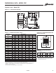
Table 22.1 - Dimensions (inches) - BDP
Blower Units - Model BDP
Figure 22.1 - Dimensional Drawings
Dimension
Model Number
Symbol
BDP 150 BDP 175 BDP 200 BDP 250 BDP 300 BDP 350 BDP 400
A 21 23-1/2 25-5/8 25-5/8 28-5/8 33-5/8 40
B 35-1/4 35-1/4 40-1/4 40-1/4 40-1/4 40-1/4 40-1/4
C 22 22 25 25 25 25 25
D 18-9/16 21-1/16 23-3/16 23-3/16 26-3/16 31-3/16 37-1/2
E 20 20 24 24 24 24 24
F 12 12 13-1/2 13-1/2 14 – –
G 6-9/16 6-9/16 7-1/2 7-1/2 7-1/2 7-1/2 7-1/2
H 17-3/8 19-7/8 22 22 25 30 36-3/8
J ➀ 5 5 5 6 6 6 6
K Mounting Holes ➁ 3/8-16 3/8-16 3/8-16 3/8-16 3/8-16 3/8-16 3/8-16
L w/ Blwr Encl & Filt Rk 62-5/8 62-5/8 69-5/8 69-5/8 69-5/8 69-5/8 69-5/8
L w/o Blwr Encl & Filt Rk 53-1/8 53-1/8 61 61 61 61 65
M ➂ 47-1/8 47-1/8 55 55 55 55 59
N ➃ 21-1/2 21-1/2 25-7/16 25-7/16 24-15/16 17-15/16 22
O 7-1/4 7-1/4 8-1/2 8-1/2 8-1/2 8-1/2 8-1/2
P 30 30 34 34 34 34 34
Q Blower Encl Ht 21-3/8 21-3/8 25-1/8 25-1/8 25-1/8 25-1/8 25-1/8
R Inlet Duct Height 20 20 23-3/4 23-3/4 23-3/4 23-3/4 23-3/4
S Center to Center
Blower Mtg. Holes
T Inlet Duct Width 27-1/2 27-1/2 32-3/4 32-3/4 32-3/4 42-7/8 42-7/8
V Blower Encl Width 29 29 34-1/4 34-1/4 34-1/4 44-3/8 44-3/8
W – – – – – 5 5
X – – – – – 16 16
AA 8 8 9 9 9 9 9
BB 7-1/4 7-1/4 7-1/4 7-1/4 7-1/4 7-1/4 7-1/4
CC – – – – – – –
DD 2-3/4 2-3/4 2-3/4 3-3/8 3-3/8 3-3/8 6-13/16
EE 56-5/8 56-5/8 63-5/8 63-5/8 63-5/8 63-5/8 63-5/8
Gas Connections ➄ 1/2 1/2 1/2 1/2 1/2 3/4 3/4
Std. Mtr. Sheave Dia. 3 3 3 3 3 3 4-1/2
Std. Blower Sheave Dia. 11 7 14 10 7 6 10
Blower Wheel Diameter 13 13 15 15 15 15 15
Approx. Weight 152 152 315 315 339 428 498
17-5/16 17-3/8 20-3/8 20-3/8 20-3/8 20-3/8 20-3/8
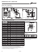
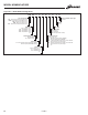
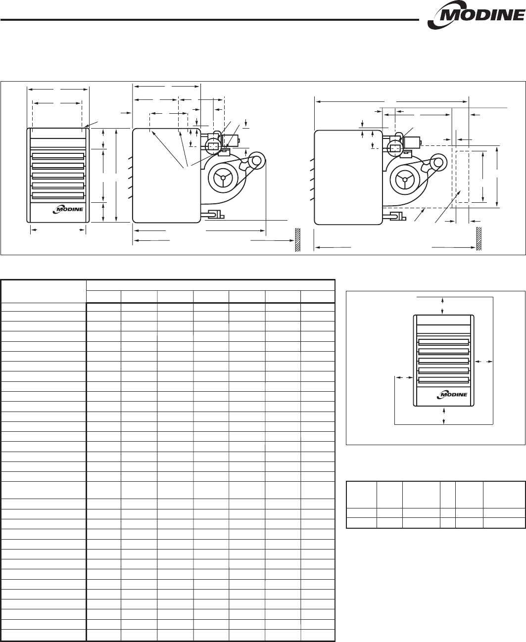
Figure 22.2 - Combustible Material and
Service Clearances
A
D
B
C
Access
Side
Table 22.2 - Combustible Material
Clearances ➀
➀ Provide sufficient room around the heater to allow for
proper combustion and operation of fan. Free area
around the heater must not be less than 1-1/2 times
the discharge area of the unit.
Access Non-Access Top of Power
Model Side Side Top Bottom Exhauster
Size (A) (B) (C) (D) (Not shown)
150-175 1 1 4 12 2
200-400 1 1 5 12 3
342844 6-189.9.indd 22 11/11/14 9:59 PM