
User's Manual

MLX
TM
Mobile Platform
Communication System
User’s Manual
Page 16 of 18
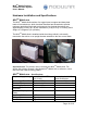
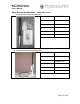
Bi-directional Amplifier, Cavity Filter and Antenna
The antenna have to be positioned such that it is the highest point on the vehicle,
then multipath is not a problem and a single omni performs 98-99% as good a
dual configuration, providing 360-degree coverage. The antennas brackets are
typically mounted on the front left and right deck or handrails as follows:
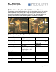
(Front right side)
(Front left side)
Bi-directional Amplifier, Filter and Antenna
– Specifications
Horizontal Pattern 360 degrees
Vertical Pattern 35 degrees
Antenna Gain 6dBi
Frequency Operation 2400- to 2484-MHz
Supply Voltage +12VDC +/- 5% Provided by the MLX
TM
Mobile Hub
Power Usage 2.6 watts
3.2 watts
Typical
100% duty
Receive (RX)
Gain 20dB (amplifier) + 6dBi of
antenna gain +/- 2dB
Supply Current <250mA
TX to RX Switching 2 uSec Typical
Transmit (TX)
AGC Gain Wide RF power input 2-20 dBm
Maximum Amplifier
Output
1 watt (30 dBm)
Supply Current <800mA
RX to TX Switching 2 uSec Typical