INS10079C - 8/14 Please contact Moen first For Installation Help, Missing or Replacement Parts (USA) 1-800-BUY-MOEN (1-800-289-6636) Mon - Fri 8:00 AM to 7:00 PM, Eastern Sat. 9:00 AM to 3:00 PM Eastern WWW.MOEN.COM/MOTIONSENSE/SUPPORT Installation Guide Guía de Instalación Guide d’installation (Canada) 1-800-465-6130 Mon - Fri 7:30 AM to 8:00 PM, Eastern WWW.MOEN.
Parts List HELPFUL TOOLS For safety and ease of faucet replacement, Moen recommends the use of these helpful tools. HERRAMIENTAS ÚTILES Para que el cambio de la llave sea fácil y seguro, Moen le recomienda usar estas útiles herramientas. OUTILS UTILES Par mesure de sécurité et pour faciliter l’installation, Moen suggère l’utilisation des outils suivants. 3/32" A. B. C. D. E. F. Faucet body Spray wand Deck gasket Pulldown hose Data cable Hose weight locator mark G. Deck plate H. Deck plate gasket I.
INS10079C - 8/14 I J K L A M B S N C V x6 O x3 x4 Q P D F 2 1 x2 R W 3 *Optional A/C Adapter 163712 (sold separately) *Adaptador C/A Optativo 163712 (en venta por separado) *Adaptateur c.a.
IMPORTANT/IMPORTANTE/IMPORTANT START UP OR RESET PROCEEDURE/PROCEDIMIENTO DE ACTIVACIÓN O REINICIO/PROCÉDURE DE DÉMARRAGE OU DE RÉINITIALISATION When starting your MotionSense kitchen faucet, observe these three easy steps: Al poner en marcha su mezcladora de cocina MotionSense, siga estos tres pasos fáciles: Pour démarrer votre robinet de cuisine MotionSense, suivre les trois étapes suivantes : 1. Remove the protective labels from the sensors on the top and the front of the spout. 1.
INS10079C - 8/14 Finished Installation/Instalación terminada/ Installation terminée 2 3 1 After installing hoses, data cable or power cable can be secured in place using supplied zip ties. Después de instalar las mangueras, el cable de datos o el cable de alimentación puede asegurarse en su lugar con las abrazaderas plásticas provistas. Après avoir installé les tuyaux, le câble de données ou le câble électrique peut être fixé en utilisant les attaches autobloquantes fournies.
1a 1b Single hole/Un orificio/Une ouverture A Three hole/Tres orificios/Trois ouvertures A G C H E E 2 1 Align Alinee Alignez 2 1 3 3 C Install faucet body (A)–including hoses, data cable (E), and deck gasket (C)–in hole on sink. Note: Installs with handle on right side only. Install faucet body (A)–including hoses, data cable (E), deck plate (G) and deck plate gasket (H)–through center hole on sink. Note: Installs with handle on right side only.
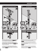
INS10079C - 8/14 2a 2b Recommended/Recomendado/Recommandé Option/Opción/Option A A 1 I 1 2 IMPORTANT IMPORTANTE IMPORTANT J 3 K 1 E IMPORTANT IMPORTANTE IMPORTANT 4 2 2 K 1 3 E E 3 2 3 E J I J J K K A A Slide support bracket (I), then mounting washer (J) up onto faucet body (A) under sink and secure with mounting nut (K). Important: thread data cable through hole in bracket (I) and open side of washer (J). Use care to make sure data cable (E) is not pinched.
3 4 3 A 1 T L 2 2 K 1 U T 2" Tighten mounting nut (K) with installation tool (T). Use screwdriver through hole in installation tool (T) to tighten firmly. Install pulldown connecting hose bracket (L) onto lower end of pulldown connecting hose (U), about 2” from end of pulldown connecting hose (U). Apriete la tuerca de montaje (K) con la herramienta de instalación (T). Use un destornillador a través del orificio en la herramienta de instalación (T) para apretar firmemente.
INS10079C - 8/14 6 5 A L A 1 1 2 1 M 3 U Slide pulldown connecting hose bracket (L) over threaded shank and secure with hose guide nut (M). Deslice la ménsula de la manguera extensible (L) sobre el vástago roscado y asegúrela con la tuerca de guía de la manguera (M). Faire glisser le support de tuyau de raccord du bec rétractable (L) sur la tige filetée et le fixer à l’aide de l’écrou du guide-tuyau (M).
7 8 12" min. (305mm) U 1 2 D Control box (O) location Ubicación de la caja de control (O) Emplacement du boîtier de contrôle (O) Attach pulldown hose (D) into quick connect on pulldown connecting hose (U) . Insert as far as possible until a “click” is heard. Tug downward to test engagement. For easier serviceability, mount control box mininum 12" (305mm) above floor. Select the desired location for control box (O).
INS10079C - 8/14 9 10 This side up Este lado hacia arriba Ce côté vers le haut 3 2 O 1 S X3 Secure control box (O) to wall with provided mounting screws (S). If installing into drywall use appropiate anchors and screws (not provided). Asegure la caja de control (O) a la pared con los tornillos de montaje provistos (S). Si la instala sobre pared en seco, utilice anclajes y tornillos apropiados (no provistos). Fixer le boîtier de contrôle (O) au mur avec les vis de montage fournies (S).
14 13 1 U O U Cold Frio Froid 1 Hot Caliente Chaud 4 2 4 Insert pulldown connecting hose (U) (number 4) into corresponding push fit connection on bottom of control box (O). Gently pull on hose to ensure connection is secure. Inserte la manguera conectora extensible (U) (número 4) en la conexión de encastre ajustado correspondiente en la parte inferior de la caja de control (O). Tire suavemente de la manguera para verificar que esté completamente insertada y segura.
INS10079C - 8/14 17a 16 O 1 Q 2 Install Zone Zona de instalación Zone d’installation N 2 F D Battery holder location Ubicación del soporte para baterías Emplacement du porte-piles Select location for battery holder (Q). Before installation, verify that the battery holder wire will reach connection on bottom of control box (O). Seleccione la ubicación del soporte para baterías (Q).
19 Mounting Option 2/ Opción de montaje 2/ Option de montage 2 Mounting Option 1/Opción de montaje 1/Option de montage 1 R R 2 R OR/ O/ OU S 4 5 1 Q 3 Q Attach battery holder (Q) to wall with hook & loop fastener (R). First, attach one side of hook and loop fastener to wall. Then attach other piece to back of battery holder. Option: Attach battery holder to wall with screw provided. Fije el soporte para baterías (Q) a la pared con la tira de velcro (R).
INS10079C - 8/14 22 23 IMPORTANT/IMPORTANTE/IMPORTANT O Before connecting battery holder, ensure that no objects are within 3 feet of faucet. Objects could interfere with start up process. Remove both protective labels from sensors on spout. Antes de conectar el soporte para baterías, asegúrese de que no haya ningún objeto a menos de 3 pies (91 cm.) de la mezcladora. La presencia de objetos puede interferir con el proceso de activación. Retire ambas etiquetas protectoras de los sensores en el surtidor.
26 27 Check to ensure wave sensor is working properly. Move hand over wave sensor to test that water will turn on. Move hand over wave sensor again to turn water off. Verifique que el sensor de ondas esté funcionando correctamente. Mueva la mano frente al sensor para ver si sale el agua. Mueva la mano frente al sensor nuevamente para cerrar el agua. S’assurer que le détecteur de mouvement fonctionne de manière appropriée.
INS10079C - 8/14 29a 29b Option Opción Option Option Opción Option To disable both sensors: Hold your hand directly above the wave sensor for approximately five (5) seconds. Water will begin to run and then turn off, indicating MotionSense Hands-Free has been disabled. To enable both sensors: Simply repeat the process, holding your hand above the wave sensor for five (5) seconds until water begins to run again. To disable Ready Sensor only: Open handle, hold hand above wave sensor for 5 seconds.
TROUBLE SHOOTING/RESOLUCIÓN DE PROBLEMAS/RÉSOLUTION DE PROBLÈMES Performance check light on control box will illuminate in the patterns shown if service is required. For assistance, call 1-800-BUY-MOEN. Performance Check/Verificación de funcionamiento/Vérification du fonctionnement La luz de comprobación de desempeño en la caja de control se iluminará siguiendo los patrones indicados si se requiere servicio. Si necesita ayuda, llame a 1-800-BUY-MOEN.
INS10079C - 8/14 A1 Low Flow/Flujo bajo/Faible débit A3 A2 2 2 3 1 Pushdown Empuje hacia abajo Pousser vers le bas 1 2 If low flow, turn off water at stops before cleaning filter. Si el flujo es bajo, corte el agua en las llaves de paso antes de limpiar el filtro. Si le débit est faible, couper l’alimentation en eau aux robinets d’arrêt avant de nettoyer le filtre. To remove in-line filter, push down on retainerring and pull up on outlet hose (#2).
B2 B1 B3 1 2 Discard Descarte Jeter If low flow, turn off water at stops before cleaning filter. Si el flujo es bajo, corte el agua en las llaves de paso antes de limpiar el filtro. Si le débit est faible, couper l’alimentation en eau aux robinets d’arrêt avant de nettoyer le filtre. Loosen screw with flathead screwdriver. Afloje el tornillo con un destornillador plano. Dévisser la vis avec un tournevis à tête plate. Pull filter off screw. Retire el filtro del tornillo. Retirer le filtre de la vis.
INS10079C - 8/14 Trouble Shooting -Water Shut-Off With Sensors Resolución de Problemas -Interrupción del agua con los sensores Résolution de problèmes - Fermeture de l'eau avec l'utilisation des détecteurs Symptom: Water keeps flowing through the spray wand when the handle is in closed position and water does not turn off by waving hand over top wave sensor.
C4 Cold Frío Froid C6 C5 Flow HOT water for 5 minutes. Deje correr el agua CALIENTE por 5 minutos. Faire couler l'eau CHAUDE pendant 5 minutes. After 5 minutes, wave your hand over top sensor (WAVE SENSOR), continue up to 5 times, pause 3 seconds between each wave (refer to step 26). Después de 5 minutos, 5 minutes, pase la mano por encima del sensor superior (SENSOR DE ONDAS), continúe hasta 5 veces, haciendo una pausa de 3 segundos entre cada pasada (Consulte el paso 26).
INS10079C - 8/14 Note: This equipment has been tested and found to comply with the limits for a Class B digital device, pursuant to part 15 of the FCC Rules. These limits are designed to provide reasonable protection against harmful interference in a residential installation. This equipment generates, uses and can radiate radio frequency energy and, if not installed and used in accordance with the instructions, may cause harmful interference to radio communications.
Garantía limitada del Sistema MotionSense™ 1. Identidad y tipos de titulares de garantía i.