
Installation Guide


2
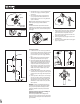
Parts List
A. Valve Housing
B. Cartridge
C. Top Plate
D. Handle Stem Bushing
E. Plaster Ground
F. Escutcheon
G. Mounting Sleeve
H. Handle
I. #10-24 Torx Screw
J. Plug Button
Lista de piezas
A. Cuerpo de la válvula
B. Cartucho
C. Plancha superior
D. Manguito del vástago del maneral
E. Plantilla de yeso
F. Chapetón
G. Manguito de montaje
H. Monomando
I. Tornillo de torsión
J. Botón de presión
Liste des pièces
A. Boîtier du robinet
B. Cartouche
C. Plaque supérieure
D. Douille de tige de poignée
E. Arrêt d’enduit
F. Rosace
G. Manchon de montage
H. Poignée
I. Vis à six lobes 10-24
J. Bouton de nition
A
B
D
C
G
I
H
J
E
F
Rough-in Body Casting
1. The distance from the supply valve center to the
center of the transfer valve must be a minimum of 12"
(305mm) to assure proper clearance of the transfer
valve escutcheon and supply valve escutcheon.
2. In the nished wall, make a minimum hole of 2-1/2"
(64mm) diameter for the transfer valve installation.
3. The plaster ground is used as a guide to help install the
valve at the proper depth within the wall. The plaster
ground should be ush with the nished wall once the
transfer valve is installed. The inlet of the transfer valve
may not be aligned with the outlet of the shower valve.
For example, the transfer valve installed with Posi-Temp
has an oset as shown in the Figure at left.
4. The Positemp Valve can be connected to the Diverter
Valve in the conguration shown at left. The top port
(Shower Port) on the Positemp Valve will need to be
capped.
"12
(305mm)
" TYP56
" TYP44
"
(12.7 mm)
1/2
FINISHED
WALL
FLOOR
Valve Front
Hot Cold
Cap Shower
Port
Valve Rear