
Installation Guide


INS288B - 7/14
3
5. With the valve castings “IN” port facing directly down,
connect the outlet of the main supply valve to the inlet
of the transfer valve using a 1/2" copper water tube. If
the supply valve has 2 outlets, one of these outlets must
be plugged.
Caution
For all installations, the cartridge must be removed from the
valve body before heating the valve. Failure to do so will result
in cartridge damage. Please refer to the instructions ‘Removing
Cartridge for CC Connection/Servicing.’
Handle Stem Position for Handle Adapter/Handle
Assembly
For correct handle position/outlet ow designation, make sure
that the handle stem ats locating mark is facing upwards and
away (opposite direction) from the inlet.
Removing Cartridge for CC Connection/Servicing
1. Remove plaster ground but do not discard.
2. Using an adjustable wrench on the ats, remove the externally threaded top plate by turning it counterclockwise (CCW).
3. Grasp the cartridge by the stem with pliers and pull the cartridge straight out.
Assembly of Outlet Connections (left)
There are 3 outlets of the transfer valve, providing 3 separate,
discrete functions. Suggested outlet designations are as
follows:
• Outlet #1: Handshower
• Outlet #2: Showerhead
• Outlet #3: Tub Spout, Additional Showerhead, or
Handshower
NOTE: Do not block any outlet. If any outlets are not to be used
(i.e. tub spout), the outlet should be plumbed into the line of
one of the other outlets. This valve is not intended to be used
as a shut-o valve. Damage to the shower system may result if
the valve is used as a shut-o valve. To prevent the potential of
cross ow, check valves must be integral to the supply valve or
installed in both hot and cold water supply lines.
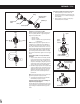
Installing Cartridge Into Transfer Valve Body (Right)
1. Place the cartridge into the transfer valve body,
positioning the 2 locating pins on the bottom of the
cartridge (Figure 1) into the 2 locating holes in the
transfer valve body (Figure 2). Assure that the stem ats
locating mark is facing upwards and away from the inlet
(Figure 3).
2. Re-assemble the top plate to the transfer valve body
by turning it clockwise until handtight (take caution
when handling the top plate threads) and then turn an
additional 1/4 turn with a wrench.
Note: The proper torque of the top plate into the transfer valve
body is 71-88 in-lbs. (8-10 N-m).
3. If the trim is to be installed at a later time, re-install the
plaster ground to protect the valve.
Handle Stem Position for Handle Adapter/Handle
Assembly
For correct handle position/outlet ow designation, make sure
that the handle stem ats locating mark is facing upwards and
away (opposite direction) from the inlet.
Outlet 2
Outlet 1 Outlet 3
Cartridge
Locating Pins
Valve Housing
Locating Holes
Stem Flats
Locating Mark
Top Plate
Figure 1
Figure 2
Figure 3
Inlet
Rear
View
Valve Housing
Cartridge
Top Plate
Stem
Handle Stem Bushing
Plaster Ground