Glove80 User Guide Date: 4 Aug 2022 DRAFT
Table of content Table of content 2 The story behind Glove80 4 What’s in the box? A look at Glove80 5 5 Quick test drive with Glove80 7 Typing with Glove80 Setting up Glove80 for comfortable typing Default key layout Indicators Caps-lock, num-lock & scroll-lock Key layout layer status Battery indicators BT and USB indicators 8 8 9 12 12 12 13 13 Operating Glove80 wirelessly Introduction Selecting BT Profile and USB-connected device Pairing with a BLE device Unpairing a BLE device Unpairing all BLE
Benefits of tenting How to adjust the tenting angle For lower angle tenting adjustments For higher angle adjustments (up to roughly 25 degrees) 25 25 26 26 Appendix: Specification 28 Appendix: ZMK 29 Appendix: Custom mounting How to custom mount Attaching Tripod Mounting Plate 30 30 31 Appendix: More Customizations Extending the Glove80 electronics Side-Car Module 32 32 34 Appendix: Compliance and Certifications USA Canada 35 35 35 Pae 3 Glove80 User Guide
The story behind Glove80 Thank you for choosing Glove80. Glove80 is not your usual keyboard. It was designed by a bunch of keyboard warriors for themselves. We were a small group of I.T. professionals who had various kinds of RSI. Without a good ergonomic keyboard our careers and quality of life would seriously suffer. We wanted and needed the most comfortable keyboard. But nothing available was good enough. Some of us were using Kinesis Advantages.
What’s in the box? - Glove80 keyboard (a pair of 2 halves) - A USB-A to USB-C cable - A set of extra M4 threaded rods for high angle tenting - 12 extra feet for high angle tenting and custom mounting - 12 extra silicone pad for high angle tenting and custom mounting - 12 half height M4 nuts for tenting - An M4 wrench - A keycap puller A look at Glove80 Glove80 is a split keyboard, consisting of a left half and a right half.
Power switch: For switching off power. Please note that it is still possible to charge the battery even when powered off.
Quick test drive with Glove80 Procedure: 1. Plug in the USB cable to the left half of your Glove80 2. Plug in the other side of the USB cable to a host, such as a PC 3. Switch on both the left and right halves by pushing in the power button on each side 4. Start typing If all goes well you should see the keystrokes showing on the PC. Your Glove80 is shipped with its battery partially charged. However, we recommend fully charging both halves before using Glove80.
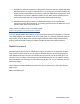
Typing with Glove80 Setting up Glove80 for comfortable typing Glove80 has been designed to encourage good typing postures. For an overview of Glove80’s ergonomic design features and the rationale behind Glove80, please read The Ergonomic Design of Glove80 Split Contoured Keyboard2 Here is a quick instruction: 1. Make sure you have a properly set up and comfortable desk and chair, or alternatively a standing desk. 2. Attach the palm rest to each half of your Glove80.
5. Glove80 is a columnar keyboard: it is designed to reduce the need for fingers stretching sideways. Most of our finger movements are to curl and uncurl. The index and the pinky fingers are each responsible for two columns, while the middle and ring fingers are each responsible for one column. Adjust the position of your palm (and if necessary the two halves of the keyboard) until you feel comfortable reaching the finger keys. 6. Glove80’s thumb cluster is unique.
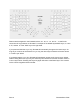
Please note that legends in the illustration above, R1…R6, C1..C6, and T1..T6, define the convention for key positions on Glove80. For example in the default layout Base Layer, LH C2R3 is “R”, and RH T1 is the “Shift” key on the right hand. If you press and hold the Layer key, Glove80 will momentarily change to the Lower Layer. As long as you continue to hold down the Layer key, the other keys will have the functions shown in “Lower Layer” below.
Single tap the Magic key, and the RGB LED indicators will show the status of caps lock, scroll lock & num lock, charge level of both batteries, status of BT Profiles and which layers are in effect. The Magic Layer is activated momentarily by holding the Magic key. While the Magic key is held, the other keys will have the functions described in the “Magic Layer” below. The Magic Layer is the layer for controlling Glove80 itself.
As you become familiar with Glove80, you may want to customize Glove80’s key layout to match your typing habits. Indicators When you tap on the Magic key, you will activate the indicators for 10 seconds.
If you are using a customized key layout, the meaning of Layer 1 to Layer 5 will depend on your definition. If your customized key layout has more than 6 layers, the status of Layer 6 or above won’t be shown. Battery indicators For more details of battery indicators, please refer to the Battery indicators section. BT and USB indicators Each BT Profile is represented by a RGB indicator.
Operating Glove80 wirelessly Introduction Glove80 is capable of wirelessly connecting to your computer, your phone or other devices through Bluetooth Low Energy (BT Low Energy or BLE). Your devices need to support Bluetooth 4.2 or above. Glove80 supports up to 4 simultaneous BLE devices being paired. Conceptually speaking, Glove80 has 4 BT Profiles, numbered BT Profile 0 to BT Profile 3. Each BT Profile can be paired with a different BLE device.
to BT Profile 1 by, on a default key layout, pressing Magic + Del. If you want to switch to the USB-connected device, on a default key layout, you can do so by pressing Magic + left-Alt Pairing with a BLE device NOTE: Before you pair with a BLE host, if you had previously paired the Glove80 with the said BLE host, you must first remove the pairing from both the BLE host and Glove80. Otherwise the pairing attempt will fail, or will cause strange problems. Please see the section on Unpairing a BLE device.
1. Does the BLE device support BT version 4.2 or later? If not, the BLE device may not be compatible with Glove80. 2. Did you previously pair Glove80 with this device? If so, you might have accidentally left a stray pairing on Glove80, Please see the section on Unpairing all BLE devices. Unpairing a BLE device Procedure: 1. Power on Glove80 2. On Glove80, select the BT Profile that was previously used to pair with the BLE device.
2. Press the key(s) to clear all bluetooth pairings for all 5 BT Profiles. On the factory default key layout, the keys are Magic + F10. 3. On all BLE devices that were previously paired, use the procedure appropriate to the operating system to remove the pairing, e.g.: a. On a Windows 10 computer, i. Go to Settings -> Bluetooth and other devices ii. Select the paired “Glove80 Left” device iii.
Battery-powered operation Glove80 can be USB-powered or battery-powered. Each half of Glove80 has a separate lithium-polymer battery. Charging To charge one half of Glove80, simply plug the half into a PC or USB charger with a USB-C cable. You can continue to use Glove80 while charging.
Configuring the RGB underglow Depending on the configuration of your Glove80, it has either RGB LEDs under all keys on both halves (“Gaming” edition), or RGB LEDs under the keys on the left half (“Standard” edition). The RGB underglow displays beautiful patterns on your Glove80. On a default key layout, the RGB underglow function is controlled by the keys highlighted in the diagram below in the Magic Layer.
Customizing key layout and swapping keycaps Customizing key layout Each of us has a different hand size and shape, typing habits, and different application needs. Glove80 and its open-source ZMK-based firmware make it easy for you to customize your Glove80 to have exactly the key layout you want. There are a few ways to change the key layout. The easiest way is to use the UI Configurator.
3. If successful, the bootloader will present a USB Mass Storage Device. As an example, on Windows you will see a File Explorer window with the name GLV80LHBOOT 4. Copy the .UF2 file into this Mass Storage Device. If successful the Mass Storage Device will disappear. 5. Next plug in the USB-A to USB-C cable to the right half of your Glove80. 6. Put the right half into bootloader mode. On the default key layout, this is done by pressing the keys Magic + ‘.
8. Copy the .UF2 file onto this Mass Storage Device. If successful the Mass Storage Device will disappear. Putting Glove80 into Bootloader for firmware loading The bootloader is the piece of software that runs immediately after you turn on a Glove80 half. Normally it will simply pass the control over to the ZMK firmware. However it also has the ability to load new ZMK firmware by presenting a USB mass storage device.
To put the left half into the bootloader mass storage device mode: a. Switch off the power switch of the left half b. Referring to the row-column key above, hold C6R6 + C3R3 (on a default key layout, Magic + E) c. While holding the two keys, switch on the power switch of the left half To put the right half into the bootloader mass storage device mode: a. Switch off the power switch of the right half b. Referring to the row-column key above, hold C6R6 + C3R3 (on a default key layout, I + PgDn) c.
damage to the key switch and/or PCB. Damage caused by excess force is not covered by the warranty. HINT: It is generally easier to slide the keycap puller onto the keycap from the side of the keycap. Some gentle wiggling might be necessary. HINT: If the keycap you need to remove is in the middle of the keyboard half, you may have to first remove other keycaps to reach it. 2. Push the correct keycaps gently onto the switches, to match the modified key layout.
Customizing the tenting angle Benefits of tenting If you press your palm flat on your desk and hold it there for a few minutes, you will feel tension on your forearms: you are experiencing forearm pronation. If you rotate your palms such that your thumb points slightly or more into the air, you should find the position more comfortable. This is the purpose of tenting. By default, Glove80 has a tenting angle that is comfortable for most people.
NOTE: We do not recommend changing the tenting angle until you have used Glove80 for a few days. Glove80 comes with a tenting angle that is comfortable for many people. It would be worthwhile to type on Glove80 for at least a few days to get a good sense of the ergonomics of Glove80, before adjusting the tenting angle. Unlike other keyboards, Glove80 allows for fine tenting angle adjustments so that you can dial in exactly the right tenting angle for you.
3. Pick 2 or 3 feet (matching the numbers in step 1), attach a silicone foot bumper to the bottom of each foot. 4. Attach a threaded rod of the length you think would work and attach to the foot, by rotating until it touches the silicone bumper. 5. Screw two M4 nuts onto the threaded rod. The first M4 nut should be screwed on hard against the foot. The second M4 nut should be loose on the threaded rod. 6. Now attach the threaded rods and feet into the legs in step 1.
Appendix: Specification Pae 28 Glove80 User Guide
Appendix: ZMK Glove80 is designed to work with the open-source ZMK firmware. The ZMK community (www.zmk.dev) maintains the incredible ZMK firmware. For more details on the ZMK features, configuration and build procedures please refer to the ZMK documentation at https://zmk.dev/docs. ZMK community has a Discord server at https://discord.com/invite/sycytVQ. The Glove80 fork of ZMK is maintained at https://github.com/moergo-sc/zmk.
Appendix: Custom mounting Glove80 is designed to facilitate custom mounting, so that you could mount your Glove80 in countless creative ways. Here are some of the possibilities: How to custom mount Procedure: 1. For the extensible legs, remove the feet by rotating them to reveal M4 studs.
2. For the non-extensible legs, use a craft knife to remove the silicone bumper, to reveal a M4 stud. 3. Attach M4 threaded rods or M4 screws and use other appropriate fasteners such as nuts to secure Glove80 onto your custom mounting mechanism. Attaching Tripod Mounting Plate MoErgo makes available mounting plates for Glove80 to easily attach to camera tripod and other mounts using the standard tripod mount screws (1/4"-20). To mount the tripod plate onto a Glove80 half: 1.
Appendix: More Customizations Extending the Glove80 electronics WARNING: Attaching custom electronics to Glove80 can damage Glove80. If you damage your Glove80 by making custom modifications, the damage will not be covered by your warranty. Skills and experience are required to develop electronics. Do this at your own risk. Specifically the use of the GPIO pin header will void your warranty. On each half of Glove80, 6 GPIO pins, GND pins and power pins are exposed via a 2x6 1.
Please note VDDH voltage changes depending on whether Glove80 is currently battery powered or usb powered. It can be anywhere from 3V to 5V. It is recommended you use a voltage regulator to power your circuit. VEXT is the voltage that nRF52840 is internally operating in. It is also the voltage of the GPIO signals. VEXT is set by the bootloader, and is typically 2.4V. Your circuit should be powered either by VDDH or VEXT. Please ensure that you are not exceeding the current limit.
Side-Car Module The underside of Glove80 provides a couple of M2 anchor points to position a “side-car” module. MoErgo provides the STEP file for an example side-car, which you are free to use and modify. https://cdn.discordapp.com/attachments/933641217596604426/996266731947434025/Glove80 _LH_Side_Car_Template_v7.step A side-car module can be used to extend your Glove80 by developing additional hardware or peripherals.
Appendix: Compliance and Certifications USA This device complies with part 15 of the FCC rules. Operation is subject to the following two conditions. (1) This device may not cause harmful interference. (2) This device must accept any interference received, including interference that may cause undesired operation. Canada This device complies with Industry Canada license-exempt RSS Standard(s). Operation is subject to the following two conditions. (1) This device may not cause harmful interference.
NOTE: This equipment has been tested and found to comply with the limits for a Class B digital device, pursuant to part 15 of the FCC Rules. These limits are designed to provide reasonable protection against harmful interference in a residential installation. This equipment generates uses and can radiate radio frequency energy and, if not installed and used in accordance with the instructions, may cause harmful interference to radio communications.