
Service manual


-25-
Revision 7/F3512
© Moffat Ltd, January 2005
E35 Turbofan Ovens
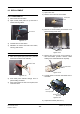
Two Bolts
Two Screws
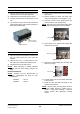
5) Withdraw old thermostat and insert new
thermostat, securing with nut.
6) Re-assemble in reverse order.
6.3.9 THERMOSTAT PROBE
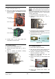
6.3.8 THERMOSTAT BOARD
1) With control panel open (refer 6.2.1) transfer
wires to new board.
2) Squeeze legs together on plastic clips holding
board and extract.
3) Push new board onto clips.
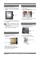
1) Remove R/H service panel (refer 6.2.1) and
oven fan baffle (refer 6.2.3).
2) Remove bracket on steam line inside oven
cavity by undoing the two screws.
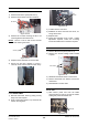
Thermostat
Board
Figure 6.3.13
Figure 6.3.14
3) Undo the 2 bolts on the flange where the
probe enters the oven (inside oven).
NOTE:
Removal of probe and its mounting plate
will require breaking of the silicone sealant.
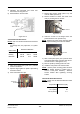
4) With control panel open (6.2.1) remove wires
from thermostat board (2 brown wires at bot-
tom left of board - refer figure 6.3.13).
5) Remove probe by drawing wires into oven.
6) Install the new probe in the reverse order.
NOTE:
Ensure probe mounting plate has RTV
silicone sealant applied to sealing face to
ensure a leak proof assembly. Remove
excess sealant after tightening securing
screws.
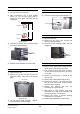
Thermostat Probe Resistances
NOTE:
Probe must be disconnected from board
for testing.
Figure 6.3.15
Dial Position O-P P-Y O-Y
Off 900 Ω 900 Ω 0 Ω
Halfway 900 Ω 450 Ω 450 Ω
Maximum 900 Ω 0 Ω 900 Ω
Resistance Between
Temperature Resistance (kΩ)
0°C (32°F) 288
37°C (99°F) 56
100°C (212°F) 6.1
Thermostat Dial Resistances
NOTE:
Dial must be disconnected from board for
testing.
O is orange wire, P is purple wire, Y is yellow
wire.
P
u
r
p
l
e
O
r
a
n
g
e
Y
e
l
l
o
w
B
r
o
w
n
B
r
o
w
n
Thermostat Board
Thermostat Dial
Figure 6.3.12