PSERIES P8M / P12M Series Proofer/Holding Cabinets (Manual Operation) Installation and Operation Manual 234277-2
MANUFACTURED BY Moffat Limited Christchurch New Zealand INTERNATIONAL CONTACTS AUSTRALIA Moffat Pty Limited E.Mail: Main Office: Service: Spares: Customer Service: vsales@moffat.com.au (tel) (03) 9518 3888 (fax) (03 9518 3833 (tel): 1800 622 216 (tel): 1800 337 963 (tel): 1800 335 315 (fax): 1800 350 281 CANADA Serve Canada Web: E.Mail: Sales: Service: www.servecanada.com info@servecanada.com (tel): 800 551 8795 (Toll Free) (tel): 800 263 1455 (Toll Free) NEW ZEALAND Moffat Limited Web: E.
Contents List P8M / P12M Turbofan Proofer / Holding Cabinets. Model Numbers Covered in this Manual P8M - Turbofan Proofer / Holding Cabinet P12M - Turbofan Proofer / Holding Cabinet - 8 Tray. - 12 Tray. Introduction ........................................................................................................... 2 Safety Information Specifications ......................................................................................................... 3 Installation...........................
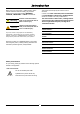
Introduction Before using your new Proofer / Holding Cabinet, please read this instruction manual carefully, pay particular attention to any information labelled ‘WARNING’, ‘CAUTION’, ‘IMPORTANT’ or ‘NOTE’ in this manual. Warning Indicates a hazardous situation which, if not avoided, will result in death or serious injury. Caution Indicates a hazardous situation which, if not avoided, will result in minor or moderate injury. This manual must be kept by the owner for future reference.
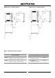
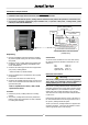
Specifications P8M Proofer / Holding Cabinet P12M Proofer / Holding Cabinet P8M / P12M Specifications Tables:- Tray Details Power Ratings P8M P12M 110-120V, 1P+N+E, 60HZ, 1.45 kW 220-240V, 1P+N+E, 50/60HZ, 1.50 kW 110-120V, 1P+N+E, 60HZ, 1.95 kW 220-240V, 1P+N+E, 50/60HZ, 1.
Installation Installation Requirements Important: • Installation shall comply with local electrical, health and safety requirements. • It is most important that this proofer / holding cabinet is installed correctly and that the operation is correct before use. • If you have any questions regarding the proper installation and / or operation of this proofer / holding cabinet , please contact your local Turbofan distributor.
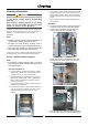
Installation Water Connection 1. A cold water supply should be connected to the water inlet located on the rear right hand side of the unit. 2. A connection elbow and sealing washer are supplied with this unit for direct connection of a ¾” ID hose, and is recommended for Water easy installation and service. Connection 3. Connect to the water supply. - Max Inlet Pressure 80psi / 550kPa. 4. Turn ‘On’ the water supply to check for water leaks.
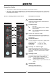
Operation Operation Guide • Turbofan Proofer / Holding Cabinets have been designed to provide simple operation. • This Proofer / Holding Cabinet is intended for use in a commercial kitchen and must only be put to the use for which it was intended, i.e. proofing and holding of food products.
Operation Operating in ‘Proof’ Mode Operating in ‘Hold’ Mode Caution Caution Take care when opening the proofer / holding cabinet door during the Proofing Mode. Let hot air and steam escape before removing or replacing food as the steam produced can cause steam burns. Some parts of this proofer / holding cabinet will become HOT during the Hold Mode and could cause burns if touched accidentally.
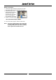
Cleaning Cleaning Guidelines e. Once a week, remove the side racks and water tank and clean any build up of product from the proofer / holding cabinet interior, using a mild anti bacterial detergent and hot water solution and a soft bristled brush. Caution Always turn ‘Off’ the electrical power supply at the mains supply before commencing cleaning. f. Dry the proofer / holding cabinet thoroughly with a soft dry cloth. This proofer / holding cabinet is not water proof.
Cleaning e. Dry the racks thoroughly with a dry cloth and polish with a soft dry cloth. Door a. Wash with warm water and a mild detergent solution using a soft sponge in straight lines up and down the inner and outer surfaces of the door. Rinse with clean, warm water and dry off. f. To refit the racks, engage the front and rear upper rack keyholes onto the upper hanger studs. g.
Cleaning Lamp Glass The P8 and P12 proofer / holding cabinets are fitted with 2 halogen lamps. These are fitted on the L/H inner side panel, behind the L/Hand side rack. e. Dry the lamp glass thoroughly with a dry cloth. NOTE: The lamp glass seal must be fitted with the flat face of the seal towards the lamp glass. f. To refit the lamp glass, screw in clockwise. Do not over tighten the lamp glass. g. Refit the L/Hand side rack as shown on the prevous page. Interior Lamps a.
Fault Finding You may encounter a problem not covered in this section, please contact your service provider who will require the following information:- This section provides a reference to the more common problems that may occur during the operation of your proofer / holding cabinet. This fault finding guide is intended to help you correct, or at least accurately diagnose problems with your proofer / holding cabinet.
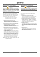
4 P4 12 E N 3 P3 L2 2 P2 OFF 1 4 3 2 1 PROOF P4 P3 P2 P1 4 4 3 2 POWER ON INDICATOR HOLD P4 P3 P2 P1 1 FUNCTION SWITCH P4 3 P3 SWITCH SETTINGS P1 L1 Ø 1 2 P2 FAN MOTOR M HUMIDITY CIRCUIT HEATING CIRCUIT LIGHT 2x25W FUSE 10A WATER SOLENOID WATER TANK THERMOSTAT P 1 1 2 WATER TANK ELEMENT 650W 120V 600W 240V 3 4 5 6 7 8 HUMIDITY ON INDICATOR WATER LEVEL FLOAT SWITCH WATER LEVEL RELAY N/O P1 P12M 1200W 120V 1200W 240V HEATING ELEMENT P8M 700W 120
Replacement Parts List Important: Only genuine authorized replacement parts should be used for the servicing and repair of this proofer / holding cabinet. The instructions supplied with the parts should be followed when replacing components. For further information and servicing instructions, contact your nearest authorized service provider or Turbofan Dealer. When ordering replacement parts, please quote the part number and the description as listed below.