
Installation Guide

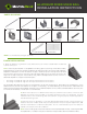

LEVEL RAIL POSTS INSTALLATION:
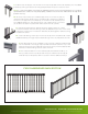
1. Measure and locate the position of the post(s) based on the project layout.
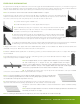
Note: If an over-the-post installation is desired, the post will need to be cut from
the standard length to accomplish this. To determine this height, place the post in
the desired locations to be installed, and mark for the bracket location as instructed
in step 7. Then, mark a line 3/4” above the bracket location marks. This will be the
location to cut the post and permit the top rail to be installed flush with the top of
the post and allow a deck board to be installed over the top of the post
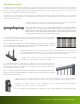
2. Install the post by attaching the aluminum mounting flange to the surface of the deck or
balcony. Position the post so the fastener will go into the floor joist, and make sure the decking
is firmly attached to the joist at the location of the post. If necessary, use wood blocking
as reinforcement underneath the decking where the posts are located. Post mounting
fasteners should be able to secure into the joist or reinforcement braces, not just the decking
itself. When installing MoistureShield Pro Rail Post on top of a wood surface, screws must be
lagged into at least 3” of solid wood. Deck boards sized 5/4” or 1 1/2” do not provide sufficient
material for a safe installation.
Note: When installing MoistureShield
®
Pro Rail Post onto treated wood surface, install the provided ACQ pad (included
in the post kit) between the post base and the treated surface.
3. Position the post to the deck surface. Four 3/8” diameter mounting
holes are provided on the mounting flange. Mark the mounting flange
hole locations and remove the post. Drill the marked locations into
the decking and reinforcement using the proper size drill required for
the fasteners being used. Remount the post. Insert the appropriate
fasteners to secure the mounting flange to the deck structure.
4. Finish by sliding the base trim to the bottom of the post to cover the mounting flange.
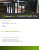
5. To install the post cap, set it in place on top of the post and strike with a rubber mallet to
drive the post cap onto the post. Silicone or water based caulking may be used to secure the
post cap and base trim.
NOTE: Post and balusters packaged separately.
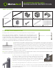
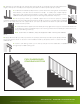
PARTS INCLUDED:
TOP RAIL WITH
CONNECTORS (1)
A
BOTTOM RAIL WITH
CONNECTORS (1)
B C D E
10” SUPPORT BLOCK (1)
F
SUPPORT BLOCK
CONNECTOR (2)
G H I J
SADDLE BRACKET (2) BOTTOM BRACKET (2) TOP RAIL CAP (2)
#10X1” SELF DRILLING
SCREW (12)
3 ½” SQUARE DRIVER BIT (1) ADHESIVE TAB (1)
ALUMINUM LEVEL RAIL
INSTALLATION INSTRUCTIONS