STAR 3000 Installation Manual MOJIX STAR 3000 SYSTEM INSTALLATION MANUAL RELEASE 2.2.X Mojix Incorporated www.mojix.
STAR 3000 Installation Manual CONTENTS Contents ........................................................................................................................................................ 2 Figures .......................................................................................................................................................... 4 Tables.........................................................................................................................................
STAR 3000 Installation Manual Appendix B: FCC Notice, STAR 3000 And eNode ..................................................................................... 43 Appendix C: FCC Notice, eMux .................................................................................................................. 44 Mojix Incorporated www.mojix.
STAR 3000 Installation Manual FIGURES Figure 1: STAR Physical Interfaces .............................................................................................................. 9 Figure 2: STAR System Topology .............................................................................................................. 10 Figure 3: Wireless STAR System Topology................................................................................................
STAR 3000 Installation Manual TABLES Table 1: eNode Connector Specification .................................................................................................... 16 Table 2: eMux Connector Specification ...................................................................................................... 18 Table 3: eMux Operating Specification ....................................................................................................... 18 Table 4: STAR Configuration ..............
STAR 3000 Installation Manual REVISION CONTROL Revision 2.2.X-1.0.0 Date 07/25/2011 Paul Barriga: Initial 2.2.X-1.0.1 08/23/2011 Paul Barriga: Added network setup 2.2.X-1.0.2 08/23/2011 Paul Barriga: Updated STAR power supply and bracket details 2.2.X-1.0.3 02/29/2012 Paul Barriga: Update FCC Statement on Page 43 2.2.X-1.0.4 03/06/2012 Paul Barriga: Added FCC Statement on Page 44 2.2.X-1.0.5 04/18/2012 Paul Barriga: Corrected zone coordinates descriptions 2.2.X-1.0.
STAR 3000 Installation Manual LEGAL NOTICES Copyright 2011 Mojix, Inc. All Rights Reserved. All content contained within this document, including text, graphics, logos, icons, images, and other materials, is the exclusive property of Mojix or its content suppliers and is protected by U.S. and international copyright laws. The compilation (meaning the collection, arrangement, and assembly) of all content within this document is the exclusive property of Mojix and is also protected by U.S.
STAR 3000 Installation Manual SYSTEM COMPONENTS The Mojix STAR system is a single network element at the enterprise edge. Based on Mojix's innovative distributed architecture, a single system consists of one or more STAR units managing up to 512 low-cost Mojix eNode transmitters.
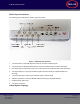
STAR 3000 Installation Manual STAR: Physical Interfaces The following picture illustrates the STAR’s physical interfaces. Figure 1: STAR Physical Interfaces 1. 1 TX Output TNC: Transmit RF Signal, 24 Volts DC, Forward Command Signal 2. 2 TX Output TNC for Wireless eNode Network: Up to two wireless forward command antenna(s) 3. 4 RX Input TNC from Antenna(s): Inputs from receive antenna array OR individual receive antenna(s) 4.
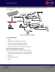
STAR 3000 Installation Manual Error! Reference source not found. illustrates the components of the STAR system topology. These items are as follows: Figure 2: STAR System Topology SYSTEM COMPONENTS 1. STAR 2. eMux: splitter and amplifier for the RF signal 3. eNode: controls up to 4 antennas to excite tags 4. Master Controller (MCON): application appliance 5.
STAR 3000 Installation Manual Command Link Receive Only Antenna Command Link Transmit Only Antenna Wireless TAR Reader External Power Supply Sensors LAN line Transmit Antenna LAN Power Supply Wireless 4 Port eNode Coaxial Cable Master Controller Tag Figure 3: Wireless STAR System Topology Mojix Incorporated www.mojix.
STAR 3000 Installation Manual STAR RECEIVER INSTALLATION STAR Receiver Installation The STAR is mechanically designed for post or wall mounting. Figure 4 illustrates the rear mounting bracket. This bracket is designed to be used with any standard VESA mounting bracket. As shown in the figure, the mounting bracket is installed directly on the STAR Receiver back plate. Installation instructions: 1. Product installation shall be conducted by a qualified installer.
STAR 3000 Installation Manual Figure 5: VESA Interface Mount Bracket Side View Figure 6: VESA Interface Mount Bracket Rear View Figure 7: VESA Interface Mount Bracket End Profile View Mojix Incorporated www.mojix.
STAR 3000 Installation Manual STAR POWER SUPPLY INSTALLATION Recommended installation of the power supply is a wall mounted configuration within 20 feet from the STAR Receiver. Wall Mount Power Supply Figure 8 shows the power supply with integrated mounting brackets. Figure 8: STAR Power Supply The wall mounted power supply requires the following hardware (not included with shipment).
STAR 3000 Installation Manual • For drywall/plaster fastening, 1/8 Molly or Toggle bolts must be used. The recommended mounting procedure is: 1. For drywall mounts, "Molly Bolts" are preferred. Alternatively, toggle bolts are a suitable option, as they offer a pull-down force more than 4X the industry standard, and are highly recommended in areas prone to seismic activity. 2.
STAR 3000 Installation Manual ENODE INSTALLATION eNode Cabling Figure 9 shows the eNode and its interfaces, each of which is detailed in the following table.
STAR 3000 Installation Manual EMUX INSTALLATION eNodes frequently are deployed with eMuxes that can connect multiple eNodes to a STAR or to another (upstream) eMux. The eMux amplifies and conditions RF signals from the STAR and provides DC power to eNodes. This section describes the steps involved to install an eMux. eMuxes should be used either when: 1. The insertion loss from long lengths of coaxial cables and eNodes is too high 2.
STAR 3000 Installation Manual used to amplify the signal. The maximum output level on an eMux for any of the 4 output ports is +20 dBm. The maximum gain of the eMux is 17 dB. Figure 11 depicts the eMux and its interfaces, showing the RF connections as well as the power supply connection. The connector specification is summarized in Table 2 below.
STAR 3000 Installation Manual MASTER CONTROLLER INSTALLATION The Master Controller (MCON) is a Linux based appliance supplied by Mojix. The hardware is based on the following specifications: • Memory : 16 GB • Hard Drives : 6 73 GB Drives in a RAID5 Configuration • Power Supplies: 2 independent, hot-swappable, minimum 675 Watt AC supplies • Processors: Two 2.8 GHz Intel Xeon Quad-Core MCON Deployment Overview The MCON connects to one or more STARs on a network through its network interface.
STAR 3000 Installation Manual Figure 14: Identification of Network Interfaces Mojix Incorporated www.mojix.
STAR 3000 Installation Manual SYSTEM NETWORK SETUP The MCON has the flexibility to configure and manage the STAR unit through a Web enabled interface called the Web Console. CONNECTING TO THE MCON The MCON by default uses DHCP for IP assignment. If a DHCP server is not found within 5 minutes from power up, the MCON uses the following default IP address. • Default Static IP: 169.254.1.1 • Default Netmask: 255.255.0.0 • Default Gateway: 169.254.1.
STAR 3000 Installation Manual Figure 15: MCON Network Configuration CHANGING STAR NETWORK SETTINGS The STAR 3000 uses DHCP for IP addressing by default. If a DHCP server is not detected within 1 minute from power up, then there are 4 temporary IP addresses assigned and remain active for 10 minutes. These addresses are as follows: • Default Ethernet 1 Address: 169.254.1.10 • Default Ethernet 1 Netmask: 255.255.0.0) • Default Ethernet 1 Secondary Address: 10.254.1.
STAR 3000 Installation Manual 2. Method 1: Connect to the STAR by entering the default IP address listed above for Ethernet 1. Figure 16 shows the graphical interace presented to the user for network setup. Enter the desired network addresses and then click on the Commit Changes button. Figure 16: STAR Web UI Network Setup 3.
STAR 3000 Installation Manual MCON CONFIGURATION Graphical User Interface The Web Console allows the user to configure and run the system. IMPORTANT: the only supported browser is Mozilla Firefox. To connect to the Web Console, enter the MCON IP address in the URL field of the browser. Not all screens are described in this version of documentation. The following screen is the landing page for the system.
STAR 3000 Installation Manual • Advanced Configuration For additional information about setting up zones and location information, see Appendix A. STAR Configuration Figure 18: STAR Configuration page Configuration Item Name IP X Pos Y Pos Z Pos Coaz Elev Roll Use Del Description The name or IP of the STAR is entered in this field. None editable. This displays the resolved IP address of the entry in the Name field.
STAR 3000 Installation Manual Figure 19: Zone Configuration page Configuration Item Name X Pos Y Pos Z Pos Type Mode Source Power Div Use Del Description The name of the Zone (unique name are required) The X coordinate relative position of the zone The Y relative position of the zone The Z relative position of the zone. Configures the operation of the Zone, please refer to Zone Type Descriptions in Table 6 Configures the mode of operation for the Zone (only applicable in DDD Zone types).
STAR 3000 Installation Manual Table 6: Zone Type Descriptions Configuration Item Shipping Description This indicates to the system that all events that are triggered by this zone will be leaving the coverage area. This indicates to the system that all events that are triggered by this zone are product that will be entering the coverage area. This indicates to the system that events that are triggered by this zone are product that will be entering or leaving the coverage area.
STAR 3000 Installation Manual Name Start delta from default (dB) Step Size (dB) Num of Steps Del The name of the Zone (unique name are required) The power profile starts from the power defined in the eNode page plus this delta. All levels are measured in dB. This indicated how much the power will be adjusted for each step size. The configured the number of steps to perform.
STAR 3000 Installation Manual Figure 22: eNode Configuration page Configuration Item Exciter Id Model Zone STAR Config X Pos Y Pos Z Pos Coaz Elev Power Sensor Staging Mobile Use Del Description The identification number of the transmitter The model type of the eNode The Zone the exciter ID is associated to The STAR the exciter ID is connected to A configuration template to aid in the configuration entry. The antenna coordinates become editable only when selecting None.
STAR 3000 Installation Manual The Location Configuration provides a mechanism to quickly configure the deployment by defining offsets from the Zone location. When configuring an antenna the location will be the geometric sum of the Zone center location and the defined location configuration.
STAR 3000 Installation Manual Figure 24: Advanced Configuration page Network Configuration The Network selection opens the configuration screen for the MCON’s network settings. Figure 25: Network Configuration page Email Configuration The Email selection opens the configuration screen for the MCON’s email settings. Users can enter an email address here where all MCON status report messages should be sent. Mojix Incorporated www.mojix.
STAR 3000 Installation Manual Figure 26: Email Configuration page Configuration Item Addresses Threshold Enabled SMTP gateway Description List of email addresses that will receive status messages. The list can be separated by a space, comma, or semicolon. Example : user1@company.com, user2@company.com Sets the minimum email alert threshold that the system will email. Enable selection. When enabled the system is active and sends mail to the configured addresses. Entry for the SMTP gateway.
STAR 3000 Installation Manual Figure 27: Redundancy Configuration page ALE Configuration The ALE selection opens the configuration screen for the MCON’s ALE configuration. On this page you can manage ECSpecs currently configured on the system. Figure 28: ALE Configuration page Configuration Item Action ECSpec ECReport POST URL Description Defines the specific operation that is desired. The support operations defined below.
STAR 3000 Installation Manual Unsubscribe (Re)Define Door Spec Unsubscribe to Define for configured zones with Dock Door Type. If the zones are added or changed, a Redefine of the is required to pick up the new doors. Define for configured zones with Location Type. If the zones are added or changed, a Redefine of the is required to pick up the new location zones.
STAR 3000 Installation Manual • State : Running/Idle • Last Known Good : Time stamp indicating the LKG configuration wrt UTC. • Firmware Version : Current BSP Version on the STAR. Figure 30: STAR Status It is possible to now use the lower toolbar to also see status on eNodes, Sensors and WSDL. For example, below screen shows status on Sensors, with the following columns: • • Columns: • txID : eNode ID to which sensor is connected. • Health : health of the sensor.
STAR 3000 Installation Manual • Channel Lock Error rate is also measured over Total,10k,1k and 100 packets. • Color coding used to indicate when error rates cross certain thresholds: • Over 50% and less than 90% - yellow • Over 90% -red • Command PER is the PER for our fsk link . • Channel Lock Error Rate is the error rate for our AFC loop. • Clear Stats sends a trigger to database to reset it => deletes all database entries.
STAR 3000 Installation Manual Figure 33: Save/Load Page HELP TAB About This About shows the current version number of MCON software. Figure 34: About Page STAR Upgrade This page provides the ability to upgrade the STAR with a firmware version supplied by Mojix. Mojix Incorporated www.mojix.
STAR 3000 Installation Manual Figure 35: STAR Upgrade Page Mojix Incorporated www.mojix.
STAR 3000 Installation Manual APPENDIX A: ENGINEERING INTERFACE - MOJO Mojo provides users with an integrated interface for both configuration and execution of the system. The functions of this interface are summarized as follows: • STAR Parameter Configuration • eNode Configuration • Inventory Program Generation • System Operation To run Mojo, the user must connect to the MCON using VNC and bring up a terminal window by clicking on the Terminal icon on the desktop.
STAR 3000 Installation Manual Figure 37: eNode Configuration (eNode Tab) The address of an eNode is written on the eNode itself as the last three digits of the serial number. The number is presented as three hexadecimal digits, for example, B89. The user must use the Enter key when entering the eNode addresses in this window for the values to be accepted. Note, when the value is accepted it will appear in parenthesis to the left of the text entry box.
STAR 3000 Installation Manual Figure 40: Auto Inventory Controls Figure 39: Transmit Parameters Figure 41: Receive Parameters Mojix Incorporated www.mojix.
STAR 3000 Installation Manual Figure 42: Select Statements Figure 43: Access Statements Figure 44: Inventory Programs Mojix Incorporated www.mojix.
STAR 3000 Installation Manual APPENDIX B: FCC NOTICE, STAR 3000 AND ENODE CAUTION: To comply with FCC RF exposure compliance requirements, a separation distance of 20 cm must be maintained between the antenna of this device and all persons. WARNING: This equipment has been tested and found to comply with the limits for Class A digital device pursuant to Part 15 of the FCC Rules.
STAR 3000 Installation Manual APPENDIX C: FCC NOTICE, EMUX WARNING: This equipment has been tested and found to comply with the limits for Class A digital device pursuant to Part 15 of the FCC Rules. These limits are designed to provide reasonable protection against harmful interference when the equipment is operated in a commercial environment.
STAR System User Manual Mojix Incorporated 11075 Santa Monica Blvd., Suite 350 Los Angeles, CA 90025 Web: www.mojix.com Tel: (877) 886-6549 E-mail: service@mojix.com Need More Help? Our product support team is comprised of individuals highly experienced in RFID deployments across a broad spectrum of application and use cases. If you are an existing customer of Mojix, please login to the secure area and submit a service request if you have additional questions.