Datasheet MK02 Bluetooth Module Datasheet MK02 Bluetooth Module (MK02D、MK02E) Datasheet MOKO TECHNOLOGY LTD. MOKO TECHNOLOGY LIMITED Version 1.2 www.mokoblue.
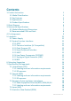
Contents 1. Product Instruction 1.1 Model Classification 1.2 Key Features 1.3 Applications 1.4 Product Specifications 2. Block Diagram 3. Mechanical Specifications 3.1 Module Mechanical Dimensions 3.2 Recommended PCB Land Pads 4. Pin Assignment 5. Interfaces 5.1 Power Supply 5.2 System Function Interfaces 5.2.1 GPIO 5.2.2 Two-wire Interface (I2C Compatible) 5.2.3 Flash Program I/O 5.2.4 Serial Peripheral Interface 5.2.5 UART 5.2.6 Low Power Comparator (LPCOMP) 5.2.7 Analog to Digital Converter (ADC) 5.2.
8. Cautions 8.1 Reflow Soldering 8.2 Usage Condition Notes 8.3 Storage Notes Revision History 20 20 21 22 22 www.mokoblue.
MK02 Bluetooth Module Datasheet 1. Product Instruction MK02 series is a powerful, highly flexible, ultra low power Bluetooth® 5 module based on Nordic® Semiconductor nRF52832 SoC solution, which has a 32bit Arm® Cortex™-M4 CPU with floating point unit running at 64MHz. MK02 module is multiprotocol capable with full protocol concurrency. It supports BLE® (Bluetooth Low Energy), including the high-speed 2 Mbps feature.
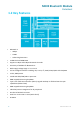
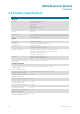
MK02 Bluetooth Module Datasheet 1.2 Key Features • Bluetooth 5 o 2Mbps o CSA#2 o Advertising Extensions • 512kB Flash and 64kB RAM • Supports 1 Mbps and 2 Mbps Bluetooth LE modes • Sensitivity of -96 dBm for Bluetooth LE • Wide supply voltage range: 1.7 V to 3.
MK02 Bluetooth Module Datasheet 1.
MK02 Bluetooth Module Datasheet 1.
MK02 Bluetooth Module Datasheet Detail Description Mechanical design Dimensions Length: 21mm±0.2mm Width: 13.8mm±0.2mm Height: 2.3mm+0.1mm/-0.
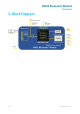
MK02 Bluetooth Module Datasheet 2. Block Diagram 6 www.mokoblue.
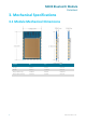
MK02 Bluetooth Module Datasheet 3. Mechanical Specifications 3.1 Module Mechanical Dimensions 7 Symbol Min. Typ. Max. Length -0.2mm 21mm +0.2mm Width -0.2mm 13.8mm +0.2mm Height (PCB only) -0.08mm 0.8mm +0.08mm Height (with shield) -0.15mm 2.3mm +0.1mm www.mokoblue.
MK02 Bluetooth Module Datasheet 3.2 Recommended PCB Land Pads MK02 PCB land pads (TOP View) 8 Symbol Typ. Half-hole Pad (Bottom) 0.8mm x 0.8mm LGA Round pad 1mm (diameter) Diameter of Half-hole 0.55mm www.mokoblue.
MK02 Bluetooth Module Datasheet 4. Pin Assignment MK02 module pin diagram(Rear View) Pin No.
MK02 Bluetooth Module Datasheet Pin No.
MK02 Bluetooth Module Datasheet 5. Interfaces 5.1 Power Supply Regulated power for the MK02 is required. The input voltage VCC range should be 1.7V to 3.6V. Suitable decoupling must be provided by external decoupling circuitry (10uF and 0.1uF). It can reduce the noise from power supply and increase power stability. 5.2 System Function Interfaces 5.2.1 GPIO The general purpose I/O is organized as one port with up to 30 I/Os enabling access and control of up to 30 pins through one port.
MK02 Bluetooth Module Datasheet 5.2.3 Flash Program I/O The module has two programmer pins, respectively SWDCLK pin and SWDIO pin. The two pin Serial Wire Debug (SWD) interface provided as a part of the Debug Access Port (DAP) offers a flexible and powerful mechanism for non- intrusive debugging of program code. Breakpoints and single stepping are part of this support. 5.2.4 Serial Peripheral Interface The SPI interfaces enable full duplex synchronous communication between devices.
MK02 Bluetooth Module Datasheet MK02 PIN NO.
MK02 Bluetooth Module Datasheet 6. Mounting Suggestion You can refer to the following references for the mounting design of the module with on-board antenna (MK02D with PCB antenna). For external antenna modules (MK02E needs to connect an external antenna to the u.FL connector), you need to refer to the external antenna design requirements.
MK02 Bluetooth Module Datasheet Other module mounting examples: Placement of resin or plastic parts: Placement of metal parts • Minimum safe distance for metal parts without seriously compromising the antenna (tuning) is 40 mm top/bottom and 30 mm left or right. • Metal close to the module antenna (bottom, top, left, right, any direction) will have degradation on the antenna performance.
MK02 Bluetooth Module Datasheet 7. Qualification and approvals 7.1 United States (FCC) The MK02 has received Federal Communications Commission (FCC) CFR47 Telecommunications, Part 15 Subpart C “Intentional Radiators” modular approval in accordance with Part 15.247 Modular Transmitter approval.
MK02 Bluetooth Module Datasheet This module is approved for installation into mobile and/or portable host platforms and must not be co-located or operating in conjunction with any other antenna or transmitter except in accordance with FCC multi-transmitter guidelines. End users must be provided with transmitter operating conditions for satisfying RF Exposure compliance. 7.
MK02 Bluetooth Module Datasheet 7.2.2 RF exposure All transmitters regulated by IC must comply with RF exposure requirements listed in RSS-102 - Radio Frequency (RF) Exposure Compliance of Radiocommunication Apparatus (All Frequency Bands). This module is approved for installation into mobile and/or portable host platforms and must not be colocated or operating in conjunction with any other antenna or transmitter except in accordance with Industry Canada's multi-transmitter guidelines.
MK02 Bluetooth Module Datasheet The MK02 module is labeled with its assigned technical conformity mark and certification number. The end product in which this module is being used must have an external label referring to the type certified module inside: Contains transmitter module with certificate number: 210-149849 7.5 Australia / New Zealand (RCM) The MK02 has been tested to comply with the AS/NZS 4268:2017, Radio equipment and systems Short range devices - Limits and methods of measurement.
MK02 Bluetooth Module Datasheet 8. Cautions 8.1 Reflow Soldering Reflow soldering is a vitally important step in the SMT process. The temperature curve associated with the reflow is an essential parameter to control to ensure the correct connection of parts. The parameters of certain components will also directly impact the temperature curve selected for this step in the process.
MK02 Bluetooth Module Datasheet Example of MOKO SMT reflow soldering: Note: The module is LGA package. Please be careful of the amount of solder paste. The module may be lifted due to excess solder. 8.2 Usage Condition Notes • Follow the conditions written in this specification, especially the recommended condition ratings about the power supply applied to this product. • The supply voltage has to be free of AC ripple voltage (for example from a battery or a low noise regulator output).
MK02 Bluetooth Module Datasheet 8.3 Storage Notes • The module should not be stressed mechanically during storage. • Do not store these products in the following conditions or the performance characteristics of the product, such as RF performance will be adversely affected: o Storage in salty air or in an environment with a high concentration of corrosive gas. o Storage in direct sunlight o Storage in an environment where the temperature may be outside the range specified.
MK02 Bluetooth Module Datasheet Integration instructions for host product manufacturers according to KDB 996369 D03 OEM Manual v01 2.1 Antennas The MK02 is an BLE Module beams signals and communicates with its antenna, which is PCB Antenna and External 2.4Ghz antenna. Antenna could not be in no-load state when module is working. During debugging, it is suggested to add 50 ohms load to the antenna port to avoid damage or performance degradation of the module under longtime no-load condition.
MK02 Bluetooth Module Datasheet Integration instructions for host product manufacturers according to KDB 996369 D03 OEM Manual v01 2.4 Limited module procedures not applicable; Single Modular Approval Request 2.5 Trace antenna designs not applicable 2.6 RF exposure considerations The equipment complies with FCC Radiation exposure limits set forth for uncontrolled environment. This equipment should be installed and operated with minimum distance 5mm between the radiator and your body. 2.
MK02 Bluetooth Module Datasheet tool. OEM shall not supply any tool or info to the end‐ user regarding to Regulatory Domain change. USERS MANUAL OF THE END PRODUCT: In the user manual of the end product, the end user has to be informed to keep at least 5mm separation with the antenna while this end product is installed and operated. The end user has to be informed that the FCC radio‐ frequency exposure guidelines for an uncontrolled environment can be satisfied.