MKL62BA Datasheet LoRaWAN Module (MKL62BA) Datasheet MOKO TECHNOLOGY LTD. Version 1.1 www.mokosmart.
Contents 1 Overview and Key Features............................................................................... 1 1.1 Brief Introduction..............................................................................................................................1 1.2 Features and Advantages.................................................................................................................. 1 1.3 Application Areas...............................................................................
LoRaWAN Module MKL62BA 1 Overview and Key Features 1.1 Brief Introduction MKL62BA is a standard LoRaWAN node module designed and manufactured by MOKO technology Ltd. The module integrates with the world-leading Nordic Semiconductor nRF52832 (BLE) and Semtech Sx1262 (LoRa) chipsets, providing ultra-low power consumption with outstanding wireless range using the LoRa radio link and local BLE connections.
LoRaWAN Module MKL62BA ▪ Asset tracking ▪ Any long range, battery powered sensor application 2 Specifications Categories Feature Implementation MCU NRF52832 Flash ARM® Cortex®-M4 32-bit processor 512KB RAM 64KB LoRa LoRaWAN 1.0.2 (End Device) Frequency Max Transmit Power MKL62BA-US915 support US915/AU915/AS923 MKL62BA-EU868 support EU868/IN865 21dBm Receive Sensitivity -137dBm@SF12 Range Up to 10 km( in free space 5dBi) Bluetooth® (BLE) V4.2 Frequency 2.402 - 2.
LoRaWAN Module MKL62BA Sleep current Antenna Options BLE (Internal) chip antenna LoRa (External) 7uA On-board ceramic chip monopole antenna-0.5 dBi U.FL (IPEX) connector for external antenna Physical Dimensions 24mm x 19mm x 2.8mm Environmental Operating -40˚ C to +85˚ C (VCC 3.
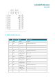
LoRaWAN Module MKL62BA Figure 2: MKL62BA module pin-out (top view) 3.
LoRaWAN Module MKL62BA Analog input 5 13 VCC Power Power supply 14 GND Power Ground 15 GND Power Ground 16 P06 Digital I/O MCU reset input 17 P07 Digital I/O General purpose I/O, reserved for I2C_SDA 18 P08 Digital I/O General purpose I/O, reserved for I2C_SCL 19 P09 20 P10 21 P15 Digital I/O 22 P18 Digital I/O 23 P20 Digital I/O 24 P22 Digital I/O General purpose I/O, reserved for SPI_CLK 25 SWDIO Digital I/O SWD debug port data 26 SWDCLK Digital input SWD
LoRaWAN Module MKL62BA 3.3 Electrical Specifications 3.3.1 Absolute Maximum Ratings Absolute maximum ratings for supply voltage and voltages on digital and analogue pins of the module are listed below; exceeding these values causes permanent damage. Parameter Minimum Maximum Unit Voltage at VCC -0.3 +3.6 V Storage temperature -40 85 ºC 3.3.2 Recommended Operating Parameters When the VCC is 3.3V, the performance will be the best. The operating voltage range is 1.9V-3.6V.
LoRaWAN Module MKL62BA 904.9 20.7 904.8991 -0.994585037 905.1 20.6 905.0992 -0.883880234 905.3 20.7 905.2991 -0.994145587 Test condition: VCC=3.3V, 25°C, SF7/BW125K Frequency/MHz Max Tx Power/dBm Test Frequency/MHz Frequency Offset/ppm 903.9 21.07 903.8992 -0.885053656 904.1 21.04 904.0991 -0.995465103 904.3 21.08 904.2991 -0.995244941 904.5 21.1 904.4992 -0.884466556 904.7 21 904.6992 -0.884271029 904.9 21.1 904.8991 -0.994585037 905.1 21.2 905.0992 -0.
LoRaWAN Module MKL62BA 912.9 20.63 912.8992 -0.876328185 913.9 20.6 913.8992 -0.875369296 914.5 20.6 914.4992 -0.87479497 3.4.2 LoRa Frequency vs Receive Sensitivity Test condition: VCC=3.3V, 25°C Frequency SF Rx Sensitivity/dBm Frequency SF Rx Sensitivity/dBm 923.3 SF7 -124 923.3 SF10 -132.2 923.9 SF7 -124.2 923.9 SF10 -132.2 924.5 SF7 -124.2 924.5 SF10 -132.1 925.1 SF7 -124.1 925.1 SF10 -132.2 925.7 SF7 -124.2 925.7 SF10 -132.2 926.3 SF7 -124.3 926.
LoRaWAN Module MKL62BA 4 Mechanical Details 4.1 MKL62BA Mechanical Details Figure 3: MKL62BA Module Mechanical drawing(unit:mm) 9 www.mokosmart.
LoRaWAN Module MKL62BA 4.2 Main PCB Layout And Module Mounting Recommended for main board layout: - Avoid running any signal line below module whenever possible. - No ground plane below antenna. - If possible, cut-off the portion of main board below antenna. Recommended module mounting: You can refer to the following references for the mounting design of the module with on-board ceramic BLE antenna. For external LoRa antenna to the u.
LoRaWAN Module MKL62BA - Ground plane shall be at least 6.5 mm from the edge of the antenna area of module. - All module GND pins MUST be connected to main board GND. Place GND vias close to module GND pads as possible. Unused PCB area on surface layer can flooded with copper but place GND via regularly to connect copper flood to inner GND plane. If GND flood copper underside the module then connects with GND vias to inner GND plane.
LoRaWAN Module MKL62BA Specification Value Unit Temperature Increase Rate <2.5 °C / s Temperature Decrease Rate Free air cooling - Preheat Temperature 0 - 150 °C Preheat Period (Typical) 40 - 90 s Soak Temp Increase Rate 0.
LoRaWAN Module MKL62BA To maintain compliance with FCC’s RF Exposure guidelines, this equipment should be installed and operated with minimum distance between 20cm the radiator your body. 2.7 Antennas BLE Antenna Designation: ceramic chip monopole antenna BLE Antenna Gain: 0.5 dBi LoRa Antenna Designation: external antenna(According to customer demand), it is suggested to add 50 ohms antenna to achieve the best performance. LoRa Antenna Gain: Max.2.0dBi 2.
LoRaWAN Module MKL62BA ▪ Increase the separation between the equipment and receiver. ▪ Connect the equipment into an outlet on a circuit different from that to which the receiver is connected. ▪ Consult the dealer or an experienced radio/TV technician for help. FCC Radiation Exposure Statement This equipment complies with FCC radiation exposure limits set forth for an uncontrolled environment. This equipment should be installed and operated with minimum distance 20cm between the radiator & your body.
LoRaWAN Module MKL62BA MOKO TECHNOLOGY LTD. 4F,Buidling2, Guanghui Technology Park, MinQing Rd, Longhua, Shenzhen, Guangdong, China Tel:86-755-23573370-829 Support_lora@mokotechnology.com https://www.mokosmart.