
Specifications


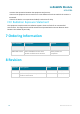

LoRaWAN Module
MKL62BA
www.mokosmart.com
11
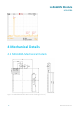
- Ground plane shall be at least 6.5 mm from the edge of the antenna area of module.
- All module GND pins MUST be connected to main board GND. Place GND vias close to module
GND pads as possible. Unused PCB area on surface layer can flooded with copper but place GND
via regularly to connect copper flood to inner GND plane. If GND flood copper underside the
module then connects with GND vias to inner GND plane.
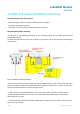
- Even when above mentioned condition is satisfied, communication performance may be
significantly deteriorated depending on the structure of the product. Bluetooth range performance
is degraded if a module is placed in the middle of the main board.
- For best BLE chip antenna performance, the module MUST be placed on the edge of the main
PCB (preferably in the corner) with the antenna facing the corner. If the module is not placed in
corner, but on edge of main PCB, the antenna routing prohibited area should be extended.
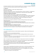
5 Reflow Soldering
Reflow soldering is a vitally important step in the SMT process. The temperature curve associated
with the reflow is an essential parameter to control to ensure the correct connection of parts. The
parameters of certain components will also directly impact the temperature curve selected for this
step in the process.
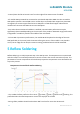
Temperature-Time Profile for Reflow Soldering
- The standard reflow profile has four zones: ①preheat, ②soak, ③reflow and ④cooling. The
profile describes the ideal temperature curve of the top layer of the PCB.
- During reflow, modules should not be above 260°C and not for more than 30 seconds.