
User manual


All operating elements and connections can be
found on the fold-out page 3.
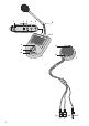
1 Operating Elements and Connections
1.1 Base station
1 Power supply jack for connection of the plug-in
power supply unit
2 Selector switch for the microphone type: set the
switch to EM (= electret microphone)
3 Jack MIC for connection of the red phono plug (13)
of the calling station
4 Jack SP for connection of the white phono plug (14)
of the calling station
5 Jack CALL-LAMP for connection of the 3.5 mm
plug (15) of the calling station
6 Electret gooseneck microphone with applied pop
protection
7 Connection for the gooseneck microphone
8 Operating indication
9 Volume control, combined with an on / off switch;
when the control is engaged at the left stop (OFF),
the system is switched off
10 TALK button, keep it pressed during an announce-
ment
1.2 Calling station
11 Operating indication
12 CALL button, when pressing the button, a signal
sound is released at the base station
13 Red phono plug for connection to the jack MIC (3)
of the base station
14 White phono plug for connection to the jack SP (4)
of the base station
15 3.5 mm plug for connection to the jack CALL-LAMP
(5) of the base station
2 Safety Notes
The units correspond to all required directives of the
EU and are therefore marked with .
It is essential to observe the following items:
G
The units are suitable for indoor use only. Protect
them against dripping water and splash water, high
air humidity, and heat (admissible ambient tempera-
ture range 0 – 40 °C).
G
Do not set the system into operation, or immediately
disconnect the power supply unit from the mains
socket if
1. there is visible damage to one of the units,
2. a defect might have occurred after a drop or simi-
lar accident,
3. malfunctions occur.
The units must in any case be repaired by skilled
personnel.
G
For cleaning only use a dry, soft cloth, never use
chemicals or water.
G
No guarantee claims for the units and no liability for
any resulting personal damage or material damage
will be accepted if the units are used for other pur-
poses than originally intended, if they are not cor-
rectly installed or operated, or not repaired in an
expert way.
3 Applications
The cable-connected intercom system ICM-20 is suit-
able e. g. for reception desks, counters, restaurants,
etc. It consists of a base station with integrated ampli-
fier, a calling station, and a plug-in power supply unit
for the power supply. Mounting material for fixing the
calling station is supplied with the system.
The base station has an integrated speaker with
volume control, a removable gooseneck microphone,
and a talk button. The calling station, with integrated
speaker and microphone, is connected via three
cables to the base station. In addition, it is equipped
with a calling button for releasing a signal sound.
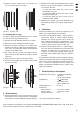
4 Mounting the Calling Station
4.1 Mounting by Glueing
Via the two supplied Velcro rings the calling station can
be glued to a glass pane.
1) Separate the rings which are connected with each
other via Velcro fasteners. Both rings have a glue-
ing layer on their rear side below a removable foil.
2) Remove the foil from one of the rings and glue the
ring onto the rear side of the calling station.
3) Remove the foil from the second ring and glue the
ring onto the desired place on the glass pane.
4) Attach the calling station with its Velcro ring to the
Velcro ring on the glass pane.
If the units are to be put out of operation
definitively, take them to a local recycling
plant for a disposal which is not harmful to the
environment.
WARNING The power supply unit is supplied with
hazardous mains voltage. Leave servic-
ing to skilled personnel only. Inexpert
handling or modification of the unit may
cause an electric shock hazard.
6
GB