
Operation Manual
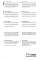


4.2 Rear panel
8 Mains jack for connection to a socket
(230 V~/ 50 Hz) via the mains cable provided
9 Support for the mains fuse
Always replace a blown fuse by one of the
same type.
10 Speaker terminals with transparent protec-
tive cover; to connect the speakers, fold up
the cover
Examples for connection see figs: 3 – 8
Either connect 100 V or 70 V speakers to the
terminals “70 V” or “100 V” and “COM” (figs. 3,
4); the maximum speaker load for the ampli-
fier is 120 W (PA-312) or 240 W (PA-324),
otherwise it may be damaged
or connect a speaker or a speaker group with
a total impedance of at least 4 Ω to the termi-
nals “4 – 16 Ω” and “COM”. Figures 5 to 8
show various ways to obtain the minimum
impedance. However, there are also other
possibilities.
11 Control MUTE LEVEL to adjust the level of
volume attenuation for the inputs MIC 2, MIC 3
(14), INPUT 4 and INPUT 5 (16) when an an-
nouncement is made via the input MIC 1 (2, 12)
12 Input MIC 1 (combined XLR / 6.3 mm jack, bal.)
to connect a microphone; for a phantom-
powered microphone, engage the button
PHANTOM POWER (13)
The jack is connected in parallel with the jack
MIC 1 (2) on the front panel. For the priority
circuit of the input MIC 1 see item 2.
13 Button PHANTOM POWER to activate the
48 V phantom power for the jack MIC 1 (12)
on the rear panel
[The jack MIC 1 (2) on the front panel is not
able to supply phantom power.]
14 Inputs MIC 2 and MIC 3 (6.3 mm jack, unbal.)
to connect microphones
15 Input TEL INPUT (plug-in screw terminal) to
connect a telephone system with line level
output or another line signal source for impor-
tant announcements.
With a signal present at this input, the signals
at the other inputs will be faded out.
To make connection easier, it is possible to
remove the terminal from its plug-in connec-
tion.
16 Inputs INPUT 4 and INPUT 5 (6.3 mm jack,
unbal.) to connect audio units with line output
(MP3 / CD player, radio, tape deck, etc.)
17 Line output OUTPUT for the mixed signal to
connect, for example, an additional ampli-
fier if more speakers are required than the
PA-312 / PA-324 can handle
5 Specifications
Output power
PA-312: . . . . . . . . . . 120 W
RMS, 160 WMAX
PA-324: . . . . . . . . . . 240 WRMS, 340 WMAX
THD: . . . . . . . . . . . . . . < 0.5 %
Outputs
Speaker: . . . . . . . . . 4 – 16 Ω, 70 / 100 V
LINE: . . . . . . . . . . . . 0.775 V/ 600 Ω
Inputs
Sensitivity/ impedance; connection
MIC 1: . . . . . . . . . . . 5 mV/ 600 Ω;
1 × XLR / 6.3 mm jack,
balanced
1 × 6.3 mm jack, unbal-
anced
MIC 2, MIC 3: . . . . . 5 mV/ 600 Ω;
6.3 mm jack,
unbalanced
INPUT 4, INPUT 5: . 350 mV/ 10 kΩ; RCA
TEL INPUT: . . . . . . . 1 V/ 10 kΩ, screw
terminals, bal.
Phantom power
for MIC 1: . . . . . . . . . . 48 V ,
to be activated
Frequency range: . . . . 50 – 16 000 Hz
Tone controls
BASS: . . . . . . . . . . . ±10 dB / 100 Hz
TREBLE: . . . . . . . . . ±10 dB / 10 kHz
S / N ratio
MIC 1 – 3: . . . . . . . . 66 dB
TEL INPUT 4 + 5: . . 80 dB
Power supply: . . . . . . . 230 V~ / 50 Hz
Power consumption
PA-312: . . . . . . . . . . 450 VA max.
PA-324: . . . . . . . . . . 740 VA max.
Ambient temperature: . 0 – 40 °C
Dimensions
PA-312: . . . . . . . . . . 430× 88 ×335 mm, 2 RS
PA-324: . . . . . . . . . . 430× 88 ×380 mm, 2 RS
Weight
PA-312: . . . . . . . . . . 7.8 kg
PA-324: . . . . . . . . . . 16.6 kg
WARNING Always fold down the cover when
operating the amplifier. A dan-
gerous high voltage is present at
the terminals; you will risk an
electric shock if you touch them.
Caution! When the phantom power has
been activated, do not connect any micro-
phone with unbalanced output; this micro-
phone may be damaged.
7
All rights reserved by MONACOR
®
INTERNATIONAL GmbH & Co. KG. No part of this instruction
manual may be reproduced in any form or by any means for any commercial use.
GB
Subject to technical modification.