MONARCH INSTRUMENT Instruction Manual ACT-2A, ACT-3A, ACT-3 Panel / Bench / Portable Tachometers / Totalizers / Ratemeters Printed in the U.S.A. Copyrighted Monarch Instrument, all rights reserved February 2005 1071-4841-124 15 Columbia Drive Amherst, NH 03031-2334 USA Phone: (603) 883-3390 Fax: (603) 886-3300 E-mail: support@monarchinstrument.com Website: www.monarchinstrument.
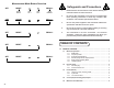
To start Menu Mode, press together SET + RESET + RECALL SET 1 SET 2 SET HI LO OFF SET LATCH SERNO SET Show serial number RESET SERNO Back to 0SCAL° FSCAL ° SET Menu Overview ACT-2A / ACT-3A / ACT-3 HYST1 * HYST2 * SET available on the ACT-3 ° Only (See section 6.
Measurement Mode Button Overview SET SET RESET ∧ ∨ RECALL Reset Alarms View Lim 1 View Lim 2 Show Max/Min ∧ RESET ∨ Safeguards and Precautions 1. Read and follow all instructions in this manual carefully, and retain this manual for future reference. 2. Do not use this instrument in any manner inconsistent with these operating instructions or under any conditions that exceed the environmental specifications stated. 3.
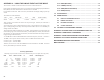
2.0 3.0 4.0 INSTALLATION and POWER ..................................................................... 5 APPENDIX D - ACT3 RS232C INTERFACE CONNECTIONS 2.1 Noisy Environments ......................................................................... 6 2.2 Adjustments ..................................................................................... 6 2.3 Sensor Connections ........................................................................
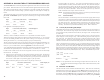
APPENDIX C – USING THE SINGLE EVENT CAPTURE MODE 6.12 BAUD (Baud Rate) ......................................................................... 13 This is to how to calculate a scale factor and to show sources of measurement error. 6.13 LOEND (Low End) .......................................................................... 13 In this example, the distance between sensors is 1 inch and we want the readings displayed in Miles Per Hour (MPH). The fastest measurement we intend to make is 130 MPH. 6.
1.0 GENERAL OVERVIEW The ACT-2A / ACT-3A / ACT-3 digital panel meters are extremely versatile instruments. The user has complete control of the unit configuration. Power may be either 115 Vac or 230 Vac (50/60 Hz), or optionally, 12 Vdc to 15 Vdc. Input signals are accepted from optical, proximity, magnetic, infrared or laser sensors, or direct TTL or external AC sources.
Once you have the correct scale factor entered, press and hold the SET button and press the RESET button once. The display will show donE and the SCALE. Release the buttons and then press the RESET button once to return the unit to normal operations. user. A moment later it measures the input frequency again. The difference of these two, scaled frequencies is divided by the time interval between the two measurements. Several measurements are averaged then displayed.
1.2.1 Auto Ranging If the instrument is set to auto range (AUTO), it will always display data to the maximum resolution, utilizing all five digits in the display. The display is always left justified, that is the data always begins in the left most digit position and the decimal point moves to the right with each increasing decade. The value 100 is thus indicated as “100.00”. The resolution then varies from 0.0001 below 10 to 10 above 100,000.
APPENDIX A - SCALING THE ACT FOR ENGINEERING DISPLAYS hysteresis would be 5% of 100 or 5. This value is then subtracted from the set point (it would be added for a low limit) so that the absolute value is 95. Thus, the alarms will trip for any input value greater or equal to 100, but will only reset when the input drops below 95. Without the hysteresis feature, the alarm relays would chatter on and off it the input varied from 99 to 101, which is undesirable.
2.0 button. The next reading will always update both values. This will keep the minimum value from showing zero unless there was a zero reading after the RECALL and RESET buttons were pressed. 9.0 CAL-N.I.S.T. N.I.S.T. Traceable Certificate of Calibration (standard on ACT-3) Thus, if you start a motor, for example, from zero, the minimum will start recording with the first reading. Usually the user will reset the minimum once the motor is up to speed.
@L1 Set Limit 1 set point Enter a maximum of 6 digits with or without decimal point followed by . Recommended values are 0 to 999990. @L2 Set Limit 2 set point Same as @L1 but for Limit 2. @H1 Set Limit 1 hysteresis Enter a maximum of 2 digits with or without decimal point followed by . Values can be from 1 to 99 only. @H2 Set Limit 2 Hysteresis Same as @H1 but for Limit 2. @G1 Set Gate Time Enter either: 0 for Standard OR 1 for Fast Followed by a .
@M1 @M2 @M3 8.4 WHITE (YELLOW - SLS) BLACK BROWN (ORANGE- SLS) BLUE BROWN BLACK Shield to COM BLUE Control commands will STOP the instrument, as they require further input and basically alter the operating parameters of the unit. Upon completion of the commands, the instrument will continue. This may cause any currently set limits to be reset or to set.
The messages are sent as standard ASCII and all messages end with a carriage return . There is no Line feed sent. However, most terminals, printers and computers have the ability to automatically add a Line feed to a carriage return.
input. Above an input of 31 Hz, the alarms respond within 66 milliseconds. Below this input they respond within (1 ¸ input frequency) seconds. NOTE: An ACT-2A will return to the main menu item DIAG at this point. The next test is for the relays. Press the SET button to turn on relay 1. The display will show ∧) 1 on. Press the RESET button to turn off relay 1. The display will show 1 off. Press the UP (∧ ∨) button to turn off button to turn on relay 2. The display will show 2 on. Press the DOWN (∨ relay 2.
6.9 HYST2 (Hysteresis Limit 2) NOTE: For applications where there is more than one pulse per revolution, the Scaling Mode must be used. Same as HYST1 but for LIMIT 2. 4.2 6.10 0SCAL (Zero Scale) The five push buttons on the front panel have multiple functions. The following sections cover the function of the buttons under normal operating conditions. Refer to the Measurement Mode Button Overview on page 24 as a quick reference guide. NOTE: This menu option will not be seen on an ACT-2A or ACT-3A.
To set a value greater than 99999, press the RECALL button causing all the decimal points to light, indicating that the displayed value must be multiplied by 10. Thus, any value up to 999990 can be set. NOTE: If the most significant digit (that on the extreme left) is zero, you cannot set the times ten mode. To escape from the EDIT Mode at any time without updating the value, simply press the RESET button.