
Manual

Page 2-9
Chapter 2 Installation and Wiring
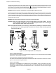
2.4 Serial Interface Option
Data can be accessed to download Configuration files or Data files using the RS232C option and a modem. The
RS485 option allows the Recorder to be installed into an existing Modbus network or it can be used to connect up
to thirty-one recorders in series. A standard DB9 Female connector is required for the RS232 to connect to an IBM
PC compatible computer using a null modem cable and the RS232 can support cable runs up to 50 feet [16 m]. The
RS485 connection is via two wire (twisted pair) cable (a DB9 Female connector is required) and can support cable
runs up to 4000 feet [1300 m].
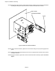
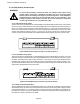
The Serial Interface contains an isolated switching unit for RS232 and RS485 access with a standard DB9 Female
connector. When switch 2 is in the ON position, RS485 is enabled. When switch 2 is in the OFF position, RS232
is enabled.
When more than one recorder are connected in a series, it is necessary to apply a termination resistor on the last
recorder. Switch 1 in the ON position applies this necessary termination resistor and should be switched to the ON
position only on the last recorder in series.
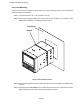
Figure 2-10 RS232/RS485 Modbus
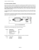
All Serial Interface connections are made through the DB9 female connector.
The RS232 Connection to the DB9 female connector are as follows:
DB9 PIN CONNECTION DIRECTION
2 RxD Receive Data In
3 TxD Transmit Data Out
4 DTR Data Terminal Ready Out
5 Common N/A
7 RTS Request To Send Out
8 CTS Clear to Send In
The RS485 (Half Duplex Mode) Connection to the DB9 female connector are as follows:
DB9 PIN CONNECTION DIRECTION
6 A- Negative Input/Output
9 B+ Positive Input/Output
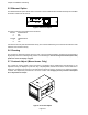
SW1
On=485 Term.
SW2
On=RS485
Off=RS232
12
ON