
Printer User Manual

G3. action Enter A to add the graphic to the printer.
G4. device Graphic storage device. Options:
F Flash (9403/9825)
N Non-volatile RAM
R Volatile RAM
T Temporary storage
NOTE: Graphics stored in flash are saved when the printer is
turned off.
G5. units Unit of measure. For bitmapped graphics, G (dots) is the only
valid option.
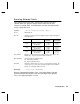
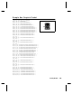
G6. row Distance between the bottom of the graphic image area and
the first bitmap line. This is usually 0, unless you want a fixed
amount of white space around the graphic image. See
"Positioning the Graphic Image," for more information.
Printer Unit of Measure Row or
End Row
Column or
End Column
9403
English (1/100 inch)
Metric (1/10 mm)
203 dpi Dots
0-599
0-1523
0-1217
0-199
0-507
0-405
9825/
9850
English (1/100 inch)
Metric (1/10 mm)
203 dpi Dots
0-1599
0-4063
0-3247
0-399
0-1015
0-811
9850
English (1/100 inch)
Metric (1/10 mm)
300 dpi Dots
0-1199
0-3047
0-3599
0-399
0-1015
0-1199
G7. column Distance between the left edge of the graphic image area and
the left edge of first bitmap line. This is usually 0, unless you
want a fixed amount of white space around the graphic image.
See "Positioning the Graphic Image," for more information.
Use the previous table for values.
G8. mode Imaging mode. Enter 0.
G9. "name" Graphic name (optional), 0-8 characters, enclose within
quotation marks.
Example
{G,99,A,R,G,0,0,0,"99Wire"
p
Adds a graphic image identified by number 99 to volatile RAM.
The graphic uses dot measurement. The image will be placed
according to the row and column parameters in the graphic field.
The imaging mode is 0 and the image is called 99Wire.
5-14
Creating Graphics