Quick Reference TC9864QR Rev. AA 6/08 Monarch® 9864™ Printer ©2008 by Avery Dennison Corp. All rights reserved.
Each product and program carries a respective written warranty, the only warranty on which the customer can rely. Avery Dennison reserves the right to make changes in the product, the programs, and their availability at any time and without notice. Although Avery Dennison has made every effort to provide complete and accurate information in this manual, Avery Dennison shall not be liable for any omissions or inaccuracies. Any update will be incorporated in a later edition of this manual.
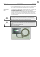
1 06/08 Rev. AA QUICK REFERENCE Getting Started 9864 Using the Printer This Quick Reference contains supply loading and general care and maintenance procedures. For more detailed information, refer to the Operator’s Handbook on the CD-Rom included with your printer. « Review the safety information in the Regulatory Compliance document on the CD-Rom before you begin. Connecting the printer WARNING! Touching live electrical parts causes exposure to hazardous electrical currents and may lead to burns.
2 06/08 Rev. AA QUICK REFERENCE Getting Started 9864 9864 V 4.10 Printer type Version number of the printer firmware Memory: 64 MB Flashcard: 32 MB Internal RAM (for example: 64 MB) Optional RAM on the Compact Flash card (for example: 32 MB) – only displayed when a Compact Flash card is in use. OFFLINE 0 JOBS Initialisation Offline mode ONLINE JOBS Online mode. The unit is ready for printing.
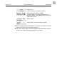
3 06/08 Rev. AA QUICK REFERENCE Getting Started 9864 Using the operator panel Display Prog button Feed button Online button Cut button [2] Operator panel Display With 32 digits and two lines, the display shows the operating conditions (modes) for parameters, values, status and errors. You can select the display language. Backlighting ensures good legibility. Button functions The buttons offer a multitude of operating functions. A logical menu structure is used for operation.
4 06/08 Rev. AA QUICK REFERENCE Getting Started 9864 y For more detailed descriptions of the button functions, see “Creating a print job” or refer to Info-Printouts and Parameters section on the CD-Rom. Remote operator panel The printer can be equipped with a remote operator panel. The printer must provide the appropriate optional connector. Refer to the Operator’s Handbook for more information. The button functions are the same as those on the standard operator panel.
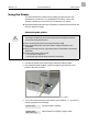
5 06/08 Rev. AA QUICK REFERENCE 9864 Loading material 1 CAUTION! Rotating axles! These can pull in and tear off hair, clothing and jewelry. – Do not operate the printer with the cover open! – Keep long hair, loose clothing, jewelry etc. away from the printer! 1. Open the cover. 2. Pull off the outer guide disk (1) of the unwinder (2). 2 3. Place the material on the unwinder with the corresponding adapter rings. The material roll should turn counter-clockwise when unwinding. 4.
6 06/08 Rev. AA QUICK REFERENCE 9864 Dispensing model only: 1 9. Guide the material under the dispenser roller (1). 10. Remove the labels from the first 10 inches of backing paper (Fig. 1). 11. Press down on the locking lever (Fig. 2) and turn it half a revolution to the rear. 12. Pull the drawing module (2) all the way out (Fig. 3). 13. Guide the backing paper under the print module to the rear (Fig. 4). P Continued on next page.
7 06/08 Rev. AA QUICK REFERENCE 9864 14. Guide the backing paper around the feed roller (1) and guide pins (2) of the drawing module to form an S shape (Fig. 1). 1 15. Replace the drawing module (Fig. 2). ¯ When replacing, the locking lever must point to the right (half a revolution open). Do not lock it until the drawing module has been pushed in all the way! 16. Wrap the end of the backing paper clockwise around the takeup reel (3) and secure it with the clip (4) (Figs. 3 and 4). 17.
8 06/08 Rev. AA QUICK REFERENCE 9864 Loading fan-folded material 1. Set the outer disk of the material unwinder to the material width. 2. Pull the material through the inlet opening (1) to the material guide printing side up. 3. See “Loading material” to continue. [1] Pull the fan-folded material through the inlet opening in the rear side and see “Loading material” to continue.
9 06/08 Rev. AA QUICK REFERENCE 9864 Changing material 1 Follow these instructions to replace the material roll. ¯ The printer must be turned on; otherwise, the printhead presses on the material. 9864 1. Set the printer to offline mode and open the cover. 2. To remove the material, press and hold the opener while pulling the material back towards the roll (Fig. 2). 2 9864 dispenser 1. Set the printer to offline mode and open the cover. 2. Tear the backing paper off (2), pull out the clip (Fig.
10 06/08 Rev. AA QUICK REFERENCE 9864 Loading a ribbon 1 1. Turn on the printer. 2. Open the cover. 3. Place the roll of ribbon on the ribbon unwind reel (1) so that it unwinds counterclockwise. 4. Place the empty ribbon core on the rewind reel (2). 5. Lead the end of the protective ribbon (yellow here) under the ribbon deflector (3) and printhead (4). 6. Pull the protective ribbon upwards and lay it over the ribbon roller (5). 2 7.
11 06/08 Rev. AA QUICK REFERENCE 9864 Settings for all printers Ribbon tension The tension of the ribbon unwind reel (1) and ribbon rewind reel (2) can be set using the red plastic hexagons on the ribbon reels. If these are turned clockwise, the tension increases (Fig. 1: dispenser version). Default settings The default settings covers a wide range of ribbon widths, but you may need to adjust the settings for very narrow or very wide ribbons.
12 06/08 Rev. AA QUICK REFERENCE 9864 Material parameters The following three parameters are used to set the material properties: Parameter Function PRINT PARAMETER > material type Sets the material type (punched or continuous) PRINT PARAMETER > material length Sets the material length PRINT PARAMETER > material width Sets the material width SYSTEM PARAMETER > light sens. type Sets the sensor type (reflex or transmission) based on the material (marks or perforations) [Tab.
13 06/08 Rev. AA QUICK REFERENCE 9864 Creating a print job There are two ways of creating a print job: by using the Microsoft® Windows® printer driver for the 9864, or by creating a text file using Easy Plug print commands. Windows printer driver 9864 printer drivers are available for different versions of Windows. You can print from nearly every Windows application using the printer drivers. However, functionality is strongly dependent on the choice of software. Label layout programs are preferred.
14 06/08 Rev. AA QUICK REFERENCE 9864 A few hints on using the USB interface: ¯ The method described here does not work in Windows 98, Windows ME or Windows NT 4.0. ¯ The sharename has to comply with the MS-DOS formatting conventions (no more than 8 characters, no symbols or spaces). Refer to “Advanced Applications” for information about Ethernet. ¯ Before sending a print job from a text program, make sure the correct printer driver is installed. ¯ Special label layout programs make this much easier.
15 06/08 Rev. AA QUICK REFERENCE 9864 Starting to print Settings for the material type The parameter settings below describe setting up the label material. When printing from a layout program, these settings are usually provided automatically by the printer driver. For your first test prints, you need to configure them manually.
16 06/08 Rev. AA QUICK REFERENCE 9864 Density To make the print darker, increase the print density as follows: 1. Press Esc while in online mode. You see Print contrast 60% 2. Press Cut/Feed to increase or decrease the heat energy of the printhead (in %). The heat energy should be kept as low as possible while retaining an acceptable printing result. A high level of heat energy reduces the life span of the printhead.
17 06/08 Rev. AA QUICK REFERENCE 9864 Care & Maintenance Regular maintenance is required to keep the printer operating properly. Safety WARNING! Maintenance and cleaning may result in hazerdous situations.
18 06/08 Rev. AA QUICK REFERENCE 9864 ¯ The printhead does not need to be removed. Mark the position of the printhead on the axle, if it is not flushed against the inner or outer plastic ring. 4. Moisten a lint-free cloth with isopropyl alcohol and wipe the printhead clean. You can also use a cleaning pen (114226). Fig. 1 Cleaning the printhead – the printhead does not need to be removed (Fig: Dispenser version). 5. Return the printhead mounting to its original position and tighten the thumb screws.
19 06/08 Rev. AA QUICK REFERENCE 9864 Cleaning the Rollers Cleaning the print roller Clean the print roller when you see adhesive buildup or dirt on the roller. 1. Turn off the printer and disconnect the power supply. 2. Remove the material and ribbon. 3. Dispenser version only: Remove the dispensing edge to access the print roller by removing both holding screws (1). Fig. 2 When using a 64xx dispenser, remove the dispensing edge to access the print roller. 1 1 4.
20 06/08 Rev. AA QUICK REFERENCE 9864 ¯ CAUTION! - Only clean the print roller with a lint-free cloth. Do not use sharp objects to clean the rollers! 6. Return the printhead mounting to its original position and tighten the thumb screws. ¯ Press the thumb screw on the tapered edge of the square axle and ensure the exact positioning of the printhead mounting on the axle. Also pay attention to the position of the printhead in relation to the edge of the label.
21 06/08 Rev. AA QUICK REFERENCE 9864 5. Return the printhead mounting to its original position and tighten the thumb screws. ¯ Press the thumb screw on the tapered edge of the square axle and ensure the exact positioning of the printhead mounting on the axle. Also pay attention to the position of the printhead in relation to the edge of the label. The printhead should be flush against the inner black plastic plug. 6. Connect the printhead cable. 7. Connect the power supply and turn on the printer.
22 06/08 Rev. AA QUICK REFERENCE 9864 Cleaning the Sensors Cleaning the gap photoelectric switch/sensor 1. Turn off the printer and disconnect the power supply. 2. Remove the material and ribbon. 3. Unscrew the two thumb screws on the printhead mounting and rotate the entire printhead mounting upwards. P See “Cleaning the Printhead” for more information. ¯ If you need to remove the printhead, mark the position of an adjusted printhead on the axle. The gap photoelectric switch can now be accessed. 4.
23 06/08 Rev. AA QUICK REFERENCE 9864 Specifications Printer - 4-inch Height: 12.0 inches (305 mm) Width: 12.8 inches (320 mm) Depth: 21.6 inches (540 mm) with cutter 19.6 (490 mm) with dispenser (peel) Weight: 48 lb. (22 kg) with cutter 52 lb. (24 kg) with dispenser (peel) Print Width: 4.3 inches (107 mm) Print Speed: 2 - 16 ips (50 - 406 mms) Printer - 5-inch Height: 12.0 inches (305 mm) Width: 12.8 inches (320 mm) Depth: 21.6 inches (540 mm) with cutter 19.
24 06/08 Rev. AA QUICK REFERENCE 9864 Printer - 8-inch Height: 12.0 inches (305 mm) Width: 18.0 inches (450 mm) Depth: 21.6 (540 mm) with cutter 19.6 (490 mm) with dispenser (peel) Weight: 61 lb. (27.5 kg) with cutter 65 lb. (29.5 kg) with dispenser (peel) Print Width: 8.
25 06/08 Rev. AA QUICK REFERENCE 9864 Supplies (Material) 4-Inch Width: 1.0 - 6.2 inches (25.4 to 154 mm) 1.0 - 5.6 inches (25.4 - 140 mm) with dispenser 5-Inch Width: 1.0 - 6.2 inches (25.4 to 154 mm) 1.0 - 5.6 inches (25.4 - 140 mm) with dispenser 6-Inch Width: 1.2 - 7.3 inches (30.2 - 185 mm) 1.2 - 6.8 inches (30.2 - 172 mm) with dispenser 8-Inch Width: 4.0 - 10.0 inches (100 - 254 mm) 4.0 - 9.5 inches (100 - 241 mm) with dispenser Min. Length: 0.2 inches (5 mm) 0.