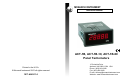
MONARCH INSTRUMENT Instruction Manual ACT-1B, ACT-1B-10, ACT-1B-60 Panel Tachometers Printed in the U.S.A. © Monarch Instrument 2001 all rights reserved 1071-4842-114 15 Columbia Drive Amherst, NH 03031-2334 USA Phone: (603) 883-3390 Fax: (603) 886-3300 E-mail: techsup@monarchinstrument.com Website: www.monarchinstrument.
Safeguards and Precautions 1. Read and follow all instructions in this manual carefully, and retain this manual for future reference. 2. Do not use this instrument in any manner inconsistent with these operating instructions or under any conditions that exceed the environmental specifications stated. 3. Be sure the power supplied to this instrument matches the specification indicated on the rear panel of the instrument. 4.
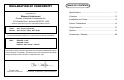
DECLARATION OF CONFORMITY As Manufacturer: TABLE OF CONTENTS Specifications ................................................................. 1 Monarch Instrument Overview ........................................................................ 2 Division of Monarch International Inc. 15 Columbia Drive, Amherst NH 03031 USA Installation and Power .................................................... 2 declares under Monarch’s sole responsibility that the product: Sensor Connections ...................
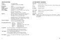
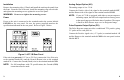
SPECIFICATIONS Range: Accuracy: Resolution: Display: Display Update: Dimensions: Power Supply: ACCESSORIES / SENSORS 5 to 99,999 RPM ROS-5W: Remote Optical Sensor ±1 RPM or 0.005% of reading T-5: Reflective Tape - 5 foot (1.5 m) roll, 0.5 inch (10 mm) wide P5-11: Proximity Sensor M-190W: Magnetic Sensor MT-190W: Magnetic Sensor with Amplifier Module IRS-5W: Infrared Sensor RLS-5W: Laser Sensor 1 RPM 5 digit, 0.56” (14 mm) high red LED Twice per second above 120 RPM 1/8 DIN by 4.
OPTIONS OVERVIEW IO: 4 to 20 mA current output AO: 0 to 5 Vdc analog output NOTE: PO: 0 to 5 V TTL compatible pulse output NOTE: CAL-N.I.S.T. Full scale RPM must be specified for the above options when ordering. Pulses out per revolution equal pulses in per revolution. N.I.S.T.
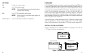
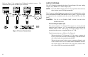
Installation Analog Output Option (AO) Remove the mounting clips, if fitted, and install the unit into the panel from the front. From the rear of the unit, install the mounting clips on each side and tighten the mounting screws against the rear of the panel. The analog output is 0 to 5 Vdc. WARNING: Do not over tighten the mounting screws. Power Power to the unit is connected to the terminals under the section labeled POWER on the rear panel.
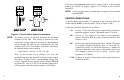
If the unit is dc powered, connect the dc supply Positive to the terminal marked L+ and the dc supply Negative or Common to the terminal marked N-. NOTE: On dc powered units, no connection is required to the terminal marked GND. SENSOR CONNECTIONS A speed sensor (not included) is connected to the terminals under the section labeled INPUT on the rear panel. Refer to Figure 2 and 3.
Refer to Figure 3 for connection of Monarch standard sensors. The connections are typical for these types of sensors. OUTPUT OPTIONS The ACT-1B may be equipped with either a Current Output (IO) or an Analog Output (AO), and/or a TTL Pulse Output (PO). NOTE: Full scale RPM settings must have been specified when ordered; these options are not field programmable.