BLDV7 Series Direct Vent Gas Fireplace Models: BLDV300N/PSC7, BLDV400n/pv7;n/pSC7, BLDV500n/pv7;n/psc7 WARNINGS If the information in these instructions are not followed exactly, a fire or explosion may result causing property damage, personal injury or loss of life. – Do not store or use gasoline or other flammable vapors and liquids in the vicinity of this or any other appliance. – WHAT TO DO IF YOU SMELL GAS • Do not try to light any appliance.
CONTENTS BLDV7 Series Gas Fireplace Thank you and congratulations on your purchase of a Monessen Fireplace. PLEASE READ THE INSTALLATION AND OPERATION INSTRUCTIONS BEFORE USING THE APPLIANCE! IMPORTANT: Read all instructions and warnings carefully before starting installation. Failure to follow these instructions may result in a possible fire hazard and will void the warranty. Important Safety Information...................................... 3 Code Approval................................................
IMPORTANT SAFETY INFORMATION BLDV7 Series Gas Fireplace INSTALLER WARNING Please leave these instructions with the appliance. or service this fireplace. • Any change to this fireplace or its controls can be dangerous. • Improper installation or use of this fireplace can cause serious injury or death from fire, burns, explosions, electrical shock and carbon monoxide poisoning.
IMPORTANT SAFETY INFORMATION & Code approval 13. Never place anything on top of fireplace. 14. Do not use any solid fuels (wood, coal, paper, cardboard, etc.) in this fireplace. Use only the gas type indicated on rating plate. 15. This appliance, when installed, must be electrically grounded in accordance with local codes or in the absence of local codes, with the National Electrical Code, ANSI/NFPA 70, or the Canadian Electrical Code, CSA C22.1. 16.
product features BLDV7 Series Gas Fireplace product SPECIFICATIONS • This appliance has been certified for use with either • • • • • • natural or propane gas. See appropriate data plates. This appliance is not for use with solid fuels. The appliance is approved for bedroom or bedsitting room installations. The appliance must be installed in accordance with local codes if any. If none exist use the current installation code. ANSI Z223.1/NFPA 54 in the USA, CSA B149 in Canada.
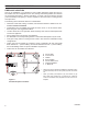
pRE-INSTALLATION INFORMATION BLDV7 Series Gas Fireplace D Rough Opening Depth V M 7" Dia. 4" Dia.
BLDV7 Series Gas Fireplace Before You Start Read this homeowner manual thoroughly and follow all instructions carefully. Inspect all contents for shipping damage and immediately inform your dealer if any damage is found. Do not install any unit with damaged, incomplete, or substitute parts. Check your packing list to verify that all listed parts have been received.
pRE-INSTALLATION INFORMATION BLDV7 Series Gas Fireplace Fireplace Location Plan for the installation of your appliance. This includes determining where the unit is to be installed, the vent configuration to be used, framing and finishing details, and whether any optional accessories (i.e. blower, wall switch, or remote control) are desired. Consult your local building code agency to ensure compliance with local codes, including permits and inspections.
clearances BLDV7 Series Gas Fireplace WARNING Clearances to combustibles Follow these instructions carefully to ensure safe installation. Failure to follow instructions exactly can create a fire hazard. The appliance cannot be installed on a carpet, tile or other combustible material other than wood flooring. If installed on carpet or vinyl flooring, the appliance shall be installed on a metal, wood or noncombustible material panel extending full width and depth of the appliance.
SECURING FIREPLACE to floor or framing BLDV7 Series Gas Fireplace The fireplace must be secured to the floor and/or to framing studs as shown in Figure 5. Use two (2) wood screws or masonry/ concrete screws to secure fireplace to the floor. Use four (4) screws to attach fireplace to framing. The side nailing flanges are 1/2" or 5/8" to accommodate different wall thickness.
VENTING INSTALLATION INFORMATION WARNING BLDV7 Series Gas Fireplace Read all instructions completely and thoroughly before attempting installation. Failure to do so could result in serious injury, property damage or loss of life. Operation of improperly installed and maintained venting system could result in serious injury, property damage or loss of life. installation precautions General Venting Consult local building codes before beginning the installation.
VENTING INSTALLATION INFORMATION BLDV7 Series Gas Fireplace General Venting Information - Termination Location INSIDE CORNER DETAIL G V H A D L V E C B V F Figure 6 Termination Locations B Fixed Closed Ope rable V B B V Fixed Closed Operable B V J A CFM145a V VENT TERMINATION B V X AIR SUPPLY INLET X M I V K X AREA WHERE TERMINAL IS NOT PERMITTED Canadian Installations1 US Installations2 CFM145a A = Clearance above grade, veranda, porch, 12” (30 cm)DV Termin Location 12
Venting INSTALLATION INFORMATION BLDV7 Series Gas Fireplace Termination Clearances Termination clearances for buildings with combustible and noncombustible exteriors. Alcove Applications* Inside Corner Outside Corner G= Combustible 6" (152 mm) G F= Combustible 6" (152 mm) Noncombustible 2" (51 mm) V Noncombustible 2" (51 mm) V C V E O F Balcony with perpendicular side wall Balcony with no side wall D C E = Min. 6” (152 mm) for non-vinyl sidewalls Min.
Venting INSTALLATION INFORMATION BLDV7 Series Gas Fireplace Twist Lock Pipes When using twist lock pipe it is not necessary to use sealant on the joints. To join twist lock pipes together, simply align the beads of the male end with the grooves of the female end, twisting the pipe until the flange on the female end contacts external flange on the male end. It is recommended that you secure the joints with three (3) sheet metal screws, however, this is not mandatory with twist lock pipe.
Vent installation WARNING BLDV7 Series Gas Fireplace Horizontal sections of this vent system require a minimum of 3" clearances to combustibles at the top of the flue and 1" clearance at the sides and bottom until the flue penetrates the outside wall. A minimum 1" clearance all around the flue is acceptable at this point of penetration. If the vertical rise is 7Z\x ft. or more, only a 1" clearance is needed on top of any horizontal run.
vent installation BLDV7 Series Gas Fireplace Vertical Sidewall Application Minimum clearance between vent pipes and combustible materials is 3" (76 mm) on top, and 1" (25 mm) on the bottom and sides unless otherwise noted. Refer to Page 15 When vent termination exits through foundations less than 20” (508 mm) below siding outcrop, the vent pipe must flush up with the siding. It is best to locate the fireplace in such a way that minimizes the number of offsets and horizontal vent length.
vent installation BLDV7 Series Gas Fireplace Vertical Sidewall Installation Twist Lock Pipe Step 1 Locate vent opening on the wall. It may be necessary to first position the fireplace and measure to obtain hole location. Depending on whether the wall is combustible or noncombustible, cut opening to size. Figure 16 (For combustible walls first frame in opening.) NOTE: When using flex vent, the opening will have to be measured according to the 1/2” (13 mm) rise in 12” (305 mm) vent run.
vent installation BLDV7 Series Gas Fireplace Step 7 Guide the vent terminations 4” and 7” collard into their respective vent pipes. Double check that the vent pipes overlap the collars by 2” (51 mm). Secure the termination to the wall with screws provided and caulk around the wall plate to weatherproof. As an alternative to screwing the termination directly to the wall, you may also use expanding plugs or an approved exterior construction adhesive.
vent installation BLDV7 Series Gas Fireplace 2. Remove soil to a depth of approximately 16” (406 mm) below base of snorkel. Install drain pipe. Install window well (not supplied). Refill hole with 12” (305 mm) of coarse gravel leaving a clearance of approximately 4” (102 mm) below snorkel. Figure 21 3. Install vent system. 4. Ensure a watertight seal is made around the vent pipe coming through the wall. 5. Apply high temperature sealant caulking (supplied) around the 4” and 7” snorkel collars. 6.
vent installation BLDV7 Series Gas Fireplace Attic Insulation Shield (7DV1AIS) 1 + 2 + 3 + 4 = 270° 1 1 2 Figure 24 Maximum Elbow Usage 2 3 Upper Floor 3 4 11” (279 mm) 4 Ceiling Installation 12” Min. FP1029 Joist FP1179 VERTICAL THROUGH-THE-ROOF INSTALLATION NOTE: For all top vent vertical through-the-roof installations, install the supplied cross-bar flue restrictor onto the top edge of the firebox flue adapter. Figure 25 1. Locate your fireplace. 2.
vent installation BLDV7 Series Gas Fireplace Horizontal Overhang 2 ft. Min. Roof Pitch H (feet) Flat to 6/12 1.0 Over 6/12 to 7/12 1.25 Over 7/12 to 8/12 1.5 Over 8/12 to 9/12 2.0 Over 9/12 to 10/12 2.5 Over 10/12 to 11/12 3.25 Over 11/12 to 12/12 4.0 Termination Vent 2 ft. Min.
fireplace installation BLDV7 Series Gas Fireplace check gas type Use proper gas type for the fireplace you are installing. If you have conflicting gas type, do not install fireplace. See dealer where you purchased the fireplace for proper fireplace for your gas type or conversion kit. A qualified installer or service person must connect appliance to gas supply. Follow all local codes.
fireplace installation Only persons licensed to work with gas piping may make the necessary gas connections to this appliance. CAUTION WARNING BLDV7 Series Gas Fireplace A manual shutoff valve must be installed upstream of the appliance. Union tee and plugged 1/8” NPT pressure tapping point should be installed upstream of the appliance. Figure 31 A listed manual shutoff valve must be installed upstream of the appliance.
BLDV7 Series Gas Fireplace Millivolt - CHECK GAS PRESSURE and Electrical installation WARNING 1. Check gas type. The gas supply must be the same as stated on the appliance’s rating decal. If the gas supply is different from the fireplace, STOP! Do not install the appliance. Contact your dealer immediately. 2. To ease installation, a 24" (610 mm) flex line with manual shut-off valve has been provided with on this appliance. Install and attach 1/2" gas line onto shut-off valve. 3.
glass removal BLDV7 Series Gas Fireplace Glass Frame Removal Remove access panel by lifting up and out. Release two clamps (500 model has three clamps) on bottom of fireplace. Figure 33 Tilt glass frame out and lift glass frame up until it clears three tabs on top of fireplace. Set glass frame aside. CAUTION 1. 2. 3. 4. Each clamp has a quick spring force. When reinstalling clamps, keep fingers clear. Glass Frame Figure 33 Removing Glass Frame ! WARNING HOT GLASS WILL CAUSE BURNS.
REMOTE WALL SWITCH & Blower INSTALLATION BLDV7 Series Gas Fireplace A remote wall switch and up to fifteen (15) feet of 18 Ga. wire may be used with this appliance. Attach the wall switch in a junction box at the desired location on the wall. Figure 35. Do not extend beyond the wall switch wire length provided. NOTE: Extended lengths of wire may cause the fireplace not to function properly. Longer length of wire is permitted if the wire is made out of larger gauge (diameter) wire.
BLDV7 Series Gas Fireplace OPTIONAL FAN/BLOWER SYSTEM 3. 4. 5. 6. 7. Remove logs. Remove grate from engine by lifting up. Remove hearth brick and wall brick panels. Disconnect the gas line to the valve. Remove screws securing engine base to firebox floor and lift engine up to remove. 8. Two (2) magnetic strips have been supplied to secure each blower Magnet to the firebox floor. Place on bottom of each blower before installing. Figure 37 9.
OPTIONAL FAN/BLOWER SYSTEM BLDV7 Series Gas Fireplace Start Position Installed Position KT505 Figure 39 Blower Installation Position NOTE: Some older units are not equipped with mounting brackets. Velcro and magnets are used to mount blowers to sidewall and floor.
OPERATING INSTRUCTIONS (Milli-volt) BLDV7 Series Gas Fireplace WARNING for your safety read before lighting If you do not follow these instruction exactly, a fire or explosion may result causing property damage, personal injury or loss of life. A. This appliance is equipped with a pilot which must be lit with built-in piezo ignitor while following these instructions exactly. B. BEFORE OPERATING smell all around the appliance area for gas.
OPERATING INSTRUCTIONS (Milli-volt) BLDV7 Series Gas Fireplace approved leak testing method You may check for gas leaks with the following methods only: • Soap and water solution • An approved leak testing spray danger • Electronic sniffer Never check for gas leak with open flame! WARNING Lighting pilot for the first time If using a soap and water solution to test for leaks, DO NOT spray solution onto control body. NOTE: Remove any excessive pipe compound from the connections.
OPERATING INSTRUCTIONS (milli-volt) BLDV7 Series Gas Fireplace Lighting burner OFF RS The “ON/OFF/RS” switch for the main burner can be found behind door of the fireplace. This switch allows you to turn on and to turn off the main burner without using the gas valve knob. Make sure the button is in the “ON” position to light the main burner. ON main burner switch On/Off/RS Switch Lighting the burner P Depress and turn knob to pilot position to keep burner off while maintaining the pilot light.
Series Gas Fireplace SIGNATURE COMMAND - CHECK GAS PRESSURE and Electrical BLDV7 installation Pressure Inlet Pressure Outlet Electrical Wiring Do not use open flame to check for gas leaks. WARNING FP1909a signature command valve alternate view 8/08 Electrical connections should only be performed by a qualified, licensed electrician. Main power must be off when connecting to main electrical power supply or performing service. All wiring shall be in compliance with all local, city and state codes.
BLDV7 Series Gas Fireplace SIGNATURE COMMAND - Electrical installation JUNCTION BOX WIRING 1. This should be done before framing the fireplace. Wire the receptacle into an electrical circuit. Wire with minimum 60° C wire in accordance with prevailing codes. 2. Remove the external junction box cover by removing the screw from the side of the outside firebox wall. Junction box was installed at the factory. 120V AC 3. The junction box cover has a factory installed “romex” style 60Hz strain relief connector.
ELECTRICAL INSTALLATION BLDV7 Series Gas Fireplace Optional AC Module To Junction Box in Fireplace Pilot { Plug in Connector Optional Blower Optional Light { White Black White Black Optional { White Black Aux. Green Connector Pin To Control Board Input 300 Watt Max.
OPTIONAL FAN BLOWER SYSTEMS The black and white wires on the AC box wiring harness are marked ‘Blower’, ‘Light’ and ‘Aux’. It is important to use the wires marked ‘Blower’ or the control will not work correctly. WARNING WARNING Electrical Grounding Instructions: This appliance is equipped with a three-prong (grounding) plug for your protection against shock hazard and should be plugged directly into a properly grounded three-prong receptacle.
OPTIONAL FAN BLOWER SYSTEMS BLDV7 Series Gas Fireplace BLOTSDV AUTOMATIC THERMOSTAT BLOWER 120VAC Receptacle Junction Box BLACK GREEN WHITE BLACK WHITE BLACK BLACK Speed Control Figure 47 BLOTSDV Blower Wiring Diagram Before installing the blower, wire the receptacle into an electrical circuit. This should be done before framing the fireplace. Wire with minimum 60° C wire in accordance FP2685 with prevailing codes.
OPERATING INSTRUCTIONS - SIGNATURE COMMAND BLDV7 Series Gas Fireplace WARNING for your safety read before lighting If you do not follow these instructions exactly, a fire or explosion may result causing property damage, personal injury or loss of lie. A. This appliance is equipped with an ignition device which automatically lights the pilot. Refer to the instructions. B. BEFORE OPERATING smell all around the appliance area for gas.
OPERATING INSTRUCTIONS - SIGNATURE COMMAND BLDV7 Series Gas Fireplace OPERATing INSTRUCTIONS 1. STOP! Read the safety information above. 2. This appliance is equipped with an ignition device which automatically lights the burner. Do not try to light the burner by hand. 3. With five (5) minutes to clear out any gas. Then smell for gas, including near the floor. If you smell gas, STOP! Follow "B" in the safety information on page 38. If you do not smell gas, go to next step. 4.
BLDV7 Series Gas Fireplace SIGNATURE COMMAND SYSTEM OPERATION INSTRUCTIONS FEATURES To Thermopile RF Receiver ON/OFF Command Center To Sensor To Sparker • Easy Access Function Operation and System Configura- tion • Operation Confirmation/Fault Diagnostic Indications (LED/ Buzzer) • ON/OFF/HI/Med/Low Operation • Optional Wall Mounting Control Board • Electronic Ignition • Pilot Lockout safety feature • Electric Power Regeneration from Thermopile to save bat• • • • • • • tery 6-hour Automatic Shut D
SIGNATURE COMMAND SYSTEM OPERATION INSTRUCTIONS BLDV7 Series Gas Fireplace SYSTEM CONFIGURATION/SETUP All System configuration/setup is done on the Command Center. NOTE: When using On/Off wall switch, the switch must be in the ON position to perform all configuration set ups at the command center. Intermittent/Standing Pilot Setup (Default intermittent) 1. Holding the ON button on the Command Center while turning on the master switch will toggle between standing pilot and intermittent pilot. 2.
BLDV7 Series Gas Fireplace SIGNATURE COMMAND SYSTEM OPERATION INSTRUCTIONS FUNCTIONS/OPERATION Turning on the fireplace 1. Turn on the master switch and wait for a beep. 2. Press the ON button on the Command Center or turn on wall switch. Pilot will light and burner will come on High setting or last memory setting (See Turning Off Fireplace below). For memory feature. Pilot Safety Lockout Function 1. If the pilot doesn’t light after sparking for 30 seconds, pilot trial lockout happens.
log & rock wool installation BLDV7 Series Gas Fireplace HEARTH BRICK placement Place the hearth brick centered in front of burner and slide back until it hits the stops on the right and left of burner. rock wool placement If the flame is blue and only in the center, turn off unit and let cool. After unit cools, remove logs. If the back holes are clear, add more rock wool to the center of the burner. Replace logs and check flame again. Save left over rock wool to refresh when cleaning later.
final installation BLDV7 Series Gas Fireplace 5. Place the left upper log (#6) at an angle by matching the rectangular notch on the bottom of this log with the rectangular protrusion on the side of the left front log (#5). The split end should point toward the front. 6. Place the small twig (#4) by having the small pointed end of the log toward the front of the fireplace and the fat end resting evenly with the pointed ends of the right and left front logs.
WARNING cleaning and maintenance Turn off gas before servicing fireplace. It is recommended that a qualified service technician perform these check-ups at the beginning of each heating season BLDV7 Series Gas Fireplace Sensor Signature Command System Pilot Thermopile Burner, Pilot and Control Compartment Keep the control compartment, logs, and burner areas surrounding the logs clean by vacuuming or brushing at least twice a year.
BLDV7 Series Gas Fireplace cleaning and maintenance Vent SysteM The fireplace and venting system should be inspected before initial use and at least annually by a qualified field service person. Inspect the external vent cap on a regular basis to make sure that no debris is interfering with the airflow. Inspect entire venting system to ensure proper function. Glass Door Thoroughly clean the inside of the glass door after using the fireplace for ten hours. Periodically clean the glass door as necessary.
troubleshooting BLDV7 Series Gas Fireplace Standing Pilot Ignition MILLIVOLT SYSTEM SYMPTOM POSSIBLE CAUSE ACTION 1. Spark ignitor will A. Wire disconnected. not light pilot after repeated triggering of B. Defective ignitor. piezo. C. No gas or low gas pressure. D. No Propane/LPG in tank 2. Pilot will not stay lit A. Defective thermocouple after carefully following lighting instructions. B. Defective valve 3. Pilot burning, valve A.
troubleshooting BLDV7 Series Gas Fireplace Standing Pilot Ignition MILLIVOLT SYSTEM SYMPTOM POSSIBLE CAUSE ACTION 4. Frequent pilot outage problem. A. Pilot flame may be too high A. Clean and adjust the pilot flame for maximum flame or too low, causing pilot impingement on thermocouple. safety to drop out 5. The pilot and main burner extinguish while in operation A. Inner vent pipe leaking exhaust gases back into system B. Horizontal vent improperly pitched C. Improper vent cap installation A.
troubleshooting BLDV7 Series Gas Fireplace SIGNATURE COMMAND SYSTEM OPERATION Install batteries and/or plug in the AC board FAULT No beep in about 8 seconds A Using battery? Make sure Command Center and the control board are connected by a 2 feet or 15 feet cable After the beep Flip the master switch (rocker switch) to the ON position Press the ON button on the Command Center No beep or no sound from the valve indicating pilot solenoid open B No sparking on the pilot C Sparking doesn’t contin
REPLACEMENT PARTS BLDV7 Series Gas Fireplace 4 3 8 5 7 2 6 FIREBOX COMPONENTS Ref. 1. 2. 3. 4. 5. 6. 6. 7. 8. 8. 8. 9. 10. 11. 12. 13. Description Qty.
REPLACEMENT PARTS BLDV7 Series Gas Fireplace Standing Pilot — Millivolt control 2I 1 2C 2T 2 5 4 6 3 8 9 7 10 11,12,13,14 743000 BLDV millivolt parts 50 74D3000
REPLACEMENT PARTS BLDV7 Series Gas Fireplace Standing Pilot — Millivolt control Ref. 1. 2. 2C. 2I. 2T. 3. 4. 5. 6. 7. 8. 9. 10. 10. Description Qty.
REPLACEMENT PARTS BLDV7 Series Gas Fireplace SIGNATURE COMMAND SYSTEM 1 2 4 3 5 6 8 7 12 13, 14, 15, 16, 17 9 20 743000 BLDV SC parts 52 74D3000
BLDV7 Series Gas Fireplace REPLACEMENT PARTS SIGNATURE COMMAND SYSTEM Item Description Qty. BLDV BLDV BLDV BLDV BLDV BLDV 300NSC7 300PSC7 400NSC7 400PSC7 500NSC7 500PSC7 1. Gas Valve Assembly 1 80D0001 80D0002 80D0001 80D0002 80D0001 80D0002 2. Pilot Assembly 1 80D0006 80D0007 80D0006 80D0007 80D0006 80D0007 3. Control Box 1 80D0018 80D0019 80D0018 80D0019 80D0018 80D0019 4. Command Center 1 80D0005 80D0005 80D0005 80D0005 80D0005 80D0005 5.
REPLACEMENT PARTS BLDV7 Series Gas Fireplace logs 5 1 6 2 3 4 Ref. 1. 2. 3. 4. 5. 6. 54 Description Qty.
VENTING COMPONENTS BLDV7 Series Gas Fireplace VERTICAL VENTING Description Vertical Vent Termination Kits Model Number Vertical Vent Termination w/ Storm Collar (flashing NOT included) 7TDVSKV Vertical Vent Termination w/ Storm Collar - 8 pack (flashing NOT included) 7TDVSKV/8 Vertical Vent Termination w/ 1/12 - 6/12 Flashing, Storm Collar and Ceiling Support Kit 7TDVSKVA* Vertical Vent Termination w/ 6/12 - 12/12 Flashing, Storm Collar and Ceiling Support Kit 7TDVSK
VENTING COMPONENTS BLDV7 Series Gas Fireplace HORIZONTAL VENTING Horizontal Vent Termination Kits Description Model Number Rear Vent Hot Touch Termination Kit w/ 10" to 16" 7TBRHTK Adjustable Termination Pipe, Firestop, and Hot Touch Termination w/ Siding Shield Up and Out Side Wall Termination Kit w/ 10" to 16" 7TDVSCTK Adjustable Termination Pipe, 90° Elbow, Firestop, and Cool Touch Termination w/ Siding Shield Rear Vent Cool Touch Termination w/ Siding Shield fo
VENTING COMPONENTS BLDV7 Series Gas Fireplace 1 7 4 8 9 HO T 5 3 2 6 11 10 VENT COMPONENTS FOR 4" X 6B\," (Simpson Duravent, Selkirk) 4" x 6Z\x" (Metal-Fab) Current Old Qty.
Requirements for the Commonwealth of Massachusetts This product must be installed by a licensed plumber or gas fitter when installed within the Commonwealth of Massachusetts. Note Regarding Vented Products Flex line installation must not exceed 36 inches and must have a T shutoff valve. Any residence with a direct vent product must have a CO detector installed in the residence.
Limited lifetime warranty policy BLDV7 Series Gas Fireplace Lifetime Warranty The following components are warranted for life to the original owner, subject to proof of purchase: Firebox, Combustion Chamber, Heat Exchanger, Grate and Stainless Steel Burners. Five Year Warranty The following components are warranted five (5) years to the original owner, subject of proof of purchase: Ceramic Fiber Logs.
Based on CSA P.4.1-09 Efficiency Ratings Model EnerGuide Ratings Fireplace Efficiency (%) BLDV300NSC7 60.2 BLDV400NV7 63.8 Recherchez dans la brochure BLDV400NSC7 68.1 les caractéristique de rendement BLDV500NV7 61.1 au gaz énergétique de foyer BLDV500NSC7 64.1 Énerguide BLDV300PSC7 64.2 Based CSA P.4.1-09 Selonon CSA P.4.1-09 BLDV400PV7 60.2 BLDV400PSC7 62.8 BLDV500PV7 64.9 BLDV500PSC7 67.9 MHSC 149 Cleveland Drive • Paris, Kentucky 40361 www.mhsc.