
Operating instructions


74D3000
8
BLDV7 Series Gas Fireplace
KT505
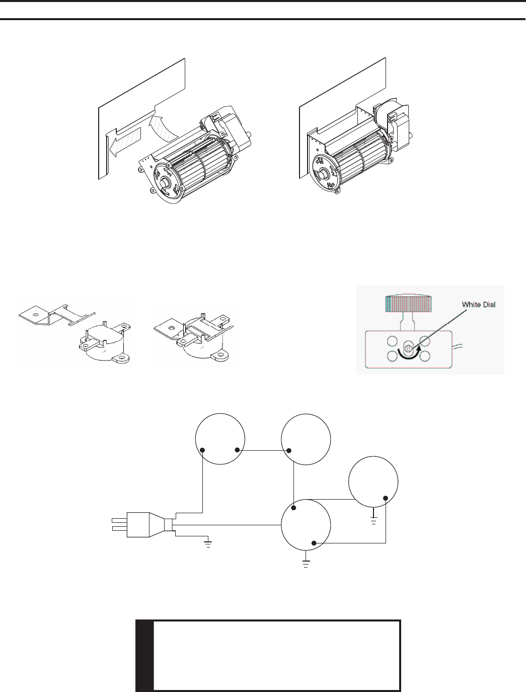
install blower
Start Position
Installed
Position
KT505
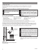
Figure 39 -
Blower Installation Position
Some older units are not equipped with mounting brackets. Velcro and magnets
are used to mount blowers to sidewall and oor.
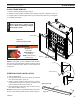
Figure 40 -
Thermal Sensor Installation
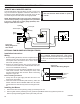
Figure 41 -
Location of White Dial on Speed Control
Blower
Motor
Blower
Motor
110/115V AC
Blower Plug
Black
White
Green
FP1910
SC blower wiring diagram
8/08
Variable
Fan Control
OFF
ON
1
2
White
(Hi Temp)
White
)pmeTiH(
White
Black
Thermal
Sensor
Figure 42 -
Blower Wiring Diagram
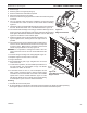
This appliance
is equipped with a three-prong (grounding) plug for
your protection against shock hazard and should be
plugged directly into a properly grounded three prong
receptacle.