INSTALLER/CONSUMER SAFETY INFORMATION PLEASE READ THIS MANUAL BEFORE INSTALLING AND USING APPLIANCE Builder Direct Vent Models: 36CDVXRRN (Rear Vent) 36CDVXTRN (Top Vent) WARNING! IF THE INFORMATION IN THIS MANUAL IS NOT FOLLOWED EXACTLY, A FIRE OR EXPLOSION MAY RESULT CAUSING PROPERTY DAMAGE, PERSONAL INJURY OR LOSS OF LIFE. FOR YOUR SAFETY Installation and service must be performed by a qualified installer, service agency or the gas supplier.
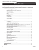
CDVX Series Direct Vent Gas Fireplace Table of Contents PLEASE READ THE INSTALLATION & OPERATING INSTRUCTIONS BEFORE USING APPLIANCE. Thank you and congratulations on your purchase of a MHSC fireplace. IMPORTANT: Read all instructions and warnings carefully before starting installation. Failure to follow these instructions fully may result in a possible fire hazard and will void the warranty. Installation & Operating Instructions General Information, Warnings, Cautions......................................
CDVX Series Direct Vent Gas Fireplace Installation & Operating Instructions This gas appliance should be installed by a qualified installer, preferably NFI or WETT (Canada) certified, in accordance with local building codes and with current CSA-B149.1 Installation codes for Gas Burning Appliances and Equipment. For USA Installations follow local codes and/or the current National Fuel Gas Code. ANSI Z223.1/NFPA 54. FOR SAFE INSTALLATION AND OPERATION PLEASE NOTE THE FOLLOWING: 1.
CDVX Series Direct Vent Gas Fireplace Installation & Operating Instructions Requirements for the Commonwealth of Massachusetts All gas fitting and installation of this heater shall only be done by a licensed gas fitter or licensed plumber.
CDVX Series Direct Vent Gas Fireplace Fireplace Dimensions - Rear Vent Minimum Rough Opening Depth * * Minimum Rough Opening Height * 34 6M” *Must be adhered to (883 mm) if using 7TCD45KT Flex Vent Kit **If using Rigid 45° with Starter Pipe 25” (635 mm) 1756 ” (435 mm) 16 6 ” (422 mm) * * * 34 5 29 6 ” 56 (8 ” ( 67 74 m *6 0 m * * 8 56 m ) 58 M” m ) 6 (1 ” ( 73 14 4 83 mm m ) m ) *4856M” (1226 mm) **41 6 ” (1051 mm) * mm) *4856M” (1226 **41 6 ” (1051 mm) Gas Line Access 1 6 ” (35 mm) Low Volta
CDVX Series Direct Vent Gas Fireplace Fireplace Dimensions - Top Vent 25” (635 mm) 1756 ” (435 mm) 16 6 ” (422 mm) m m ) (7 29 40 56 m ” m ) 6 ”( 14 83 Minimum Rough Opening Height 58 41 6 ” (1051 mm) 41 6 ” (1051 mm) Minimum Rough Opening Depth 34 6M” (883 mm) Gas Line Access 35” (889 mm) 8” (203 mm) 33” (838 mm) 356M” (83 mm) Low Voltage Access 1 6 ” (35 mm) 856O” (216 mm) 7 6 ” (187 mm) CAUTION: *Maintain minimum 1” clearance between combustible header and vent pipe.
CDVX Series Direct Vent Gas Fireplace Locating Your Fireplace V W Finish Wall X Y Y A E B Noncombustible Material 3/4” (19 mm) Scribe Moulding for use with MHSC Cabinets Standoff X C Y Z D X A B B C D E F Hood LU584-R Fig. 3 Locate gas fireplace. Fireplace LU584-R Locating unit Top of Combustion Chamber A) Flat on wall B) Cross corner C)2/23/01 **Island sta D) Room divider E) Flat on wall corner F) Chase installation Y) Refer to “Clearance to Combustibles” Section NOTE: (Fig.
CDVX Series Direct Vent Gas Fireplace Hearth A hearth is not mandatory but is recommended for aesthetic purposes. We recommend a noncombustible hearth which projects out 12” (305 mm) or more from the front of the fireplace.
CDVX Series Direct Vent Gas Fireplace Gas Specifications Model Fuel Gas Control 36CDVXRRN Nat Millivolt 36CDVXRRP* Prop Millivolt 36CDVXTRN Nat Millivolt 36CDVXTRP* Prop Millivolt *Using conversion kit 1/2” Gas Supply Max. Input BTU/h 21,000 21,000 21,000 21,000 Min. Input BTU/h 14,700 15,750 14,700 15,750 Gas Inlet and Manifold Pressures Natural LP (Propane) Inlet Minimum 5.5” w.c. 11.0” w.c. Inlet Maximum 14.0” w.c. 14.0” w.c. Manifold Pressure 3.5” w.c. 10.0” w.c.
CDVX Series Direct Vent Gas Fireplace 120V Electrical Hook Up The fireplace, when installed, must be electrically connected and grounded in accordance with local codes or, in the absence of local codes, with the current CSA C22.1 Canadian Electrical Code. For USA installations follow local codes and the national electrical code ANSI/ NFPA No. 70. 4. Insert the house wire through the connector on the cover plate. 5. Secure the wires from the receptacle to the incoming line. 6.
CDVX Series Direct Vent Gas Fireplace General Venting Information - Termination Location INSIDE CORNER DETAIL G V H A N N D L V E C B B V F Ýi` Ãi` Ope V B CFM145a V VENT TERMINATION B V Operable rable B V V Fixed Closed B J X A X AIR SUPPLY INLET M I V K X AREA WHERE TERMINAL IS NOT PERMITTED Canadian Installations1 US Installations2 CFM145a A = Clearance above grade, veranda, porch, 12” (30cm) 12” (30cm) DV Termin Location 5/01/01 Rev.
CDVX Series Direct Vent Gas Fireplace Termination Clearances Termination clearances for buildings with combustible and noncombustible exteriors. Alcove Applications* Inside Corner Outside Corner G= Combustible 6" (152 mm) G F= Combustible 6" (152 mm) Noncombustible 2" (51 mm) V Noncombustible 2" (51 mm) V C V E O F Balcony with perpendicular side wall Balcony with no side wall D C E = Min. 6” (152 mm) for non-vinyl sidewalls Min. 12” (305 mm) for vinyl sidewalls O = 8’ (2.4 m) Min. M M No.
CDVX Series Direct Vent Gas Fireplace Twist Lock Pipes 30 When using ��������������������������������������������� MHSC����������������������������������������� twist-lock pipe, it is not necessary to use sealant on the joints. The only areas of the venting system that need to be sealed with high temperature silicone sealant are the sliding joint of any telescopic vent section used in the system.
CDVX Series Direct Vent Gas Fireplace Vent Opening for Combustible Wall When using all venting except 7TCRVT1320 20" (508 mm) Max. 9³⁄₈” (240 mm) 9³⁄₈” (240 mm) Framing Detail Top View Straight Venting FP1598 Fig. 15 Rear vent applications.
CDVX Series Direct Vent Gas Fireplace Termination Finished Wall Secure with Screw Vent Termination C L to Floor Flex Section Appliance 2956O” Collars (749 mm) CL 22” (559 mm) Firestop FP1473 FP1005a Fig. 20 Grasp the vent pipe close to the collar and bend to 45° angle. Do not exceed 45°. Fig. 19 Side view of final unit location.
CDVX Series Direct Vent Gas Fireplace Screw Screws Flex Vent Collar 24Z\x” (622 mm) 13” - 20” (330 - 508 mm) FP1604 Fig. 21 Bend flex pipe up 90° as close to fireplace as possible. Corner Framing &0 REAR FLEX VENT Do Not Exceed 45° Bend FP1605a Fig. 24 The centerline of the termination must be 24Z\x” (622 mm) off the floor. 3. Proceed with Step 3 of “Rear Wall Vent Application *Exterior Outside Wall&0 A 20” to 32” (508-813 mm) from Rear of Unit” section (below).
CDVX Series Direct Vent Gas Fireplace needs to have an immediate rise before going horizontal. NOTE: Be careful not to distort the outer flex as this will affect the performance of the fireplace. 6. Secure the collar to the firestop by bending the tab out on the firestop and running a screw through the tab and collar. 7. From outside the house, slide the termination onto the collars sticking through the firestop. 8. Secure the termination to the house with the four (4) screws provided.
CDVX Series Direct Vent Gas Fireplace Example: Elbow 1 = 90˚ 4 Elbow 2 = 45˚ Elbow 3 = 45˚ Elbow 4 = 90˚ Total angular variation = 270˚ Ensure Pipes are Concentric 8 o 1 + 2 + 3 + 4 = 270 1 2 3 7TCDV90 CFM143a Fig. 30 Always start vertical run with 7TCDV90 on 36CDVR CFM143 unts. 2/2/01 sta CFM132 Fig. 29 Maximum numberCFM132 of elbows. Insert Rear Vent Sidewall •IMPORTANT• Minimum clearance between vent pipes and combustible materials is one (1”) inch (25 mm) on bottom, sides and top.
CDVX Series Direct Vent Gas Fireplace High Temperature Sealant X Below Grade Installation When it is not possible to meet the required vent terminal clearances of 12” (305 mm) above grade level a snorkel vent kit #7TDVSNORK is required. It allows installation depth of down to 7” (178 mm) below grade level. The 7” is measured from the center of the horizontal vent pipe as it penetrates through the wall.
CDVX Series Direct Vent Gas Fireplace Do not back fill around snorkel. A clearance of at least 4” (102 mm) must be maintained between the snorkel and the soil. If the foundation is recessed, use recess brackets (not supplied) for securing lower portion of the snorkel. Fasten brackets to wall first, then secure to snorkel with self drilling #8 x 1/2 sheet metal screws. It will be necessary to extend vent pipes out as far as protruding wall face. (Fig.
CDVX Series Direct Vent Gas Fireplace Attic Insulation Shield Vent Termination Roof Storm Collar 2’ Min. Roof Flashing Roof Support Attic Insulation 50’ Shield (15 m) Attic Insulation Joists Joist Joists Ceiling Installation 11" 11" Upper Floor Joist Firestop Spacer FP1022 Fig. 39 Typical straight-up installation. Nails (4) FP1022 Typical Straight Up Installation 1/26/00 djt CFM100 Fig. 38 Place firestop spacer(s) and secure.
CDVX Series Direct Vent Gas Fireplace 36CDVXT Vertical Venting 36 CDVXT Top Vent Baffle How to Use the Vent Graph The 36CDVXT is shipped with a restrictor installed in the unit. This allows for a better flame when installing a vertical venting configuration. Below is a rough estimate of opening positions based on vent length. This is a guide. More fine tuning can be done by a qualified installer.
CDVX Series Direct Vent Gas Fireplace Vertical Sidewall Applications 3' (914mm) Since it is very important that the venting system maintain its balance between the combustion air intake and the flue gas exhaust, certain limitations as to vent configurations apply and must be strictly adhered to. The vent graph showing the relationship between vertical and horizontal side wall venting will help to determine the various dimensions allowable.
CDVX Series Direct Vent Gas Fireplace X Example: Elbow 1 Elbow 2 Elbow 3 Elbow 4 = = = = 90° 45° 45° 90° 4 Total angular variation = 270° 1 + 2 + 3 + 4 = 270° 3 1 2 FP1241 Fig. 50 Horizontal length requirement. Always install horizontal venting on a level plane. FP1239 Fig. 48 Maximum number of elbow degrees. STEP 2 Place fireplace into position. (Fig. 49) Measure the vertical height (X) required from the base of the flue collars to the center of the wall opening.
CDVX Series Direct Vent Gas Fireplace Below Grade Installations When it is not possible to meet the required vent terminal clearances of 12” (305 mm) above grade level a snorkel vent kit is recommended. It allows installation depth of down to 7” (178 mm) below grade level. The 7” is measured from the center of the horizontal vent pipe as it penetrates through the wall. If venting system is installed below ground, we recommend a window well with adequate and proper drainage.
CDVX Series Direct Vent Gas Fireplace Zero Clearance Sleeve (if required) Screws 7TDVSNORK (Snorkel) Firestop 4” (102mm) Clearance Min. 7” Pipe Max. Height 40' (12m) Window Well 24” (610mm) Minimum* Max. 10' (3m) Min. Height 756O' (2.3m) Gravel Drain Foundation Wall *A minimum of 24” (610mm) vertical pipe must be installed when using the 7TDVSNORK Kit. *The 22” (559mm) vertical rise (center to center) of the snorkel may be included for calculationof max. horizontal run.
CDVX Series Direct Vent Gas Fireplace 8. Install appropriate pipe sections until the venting is above the flashing. (Fig. 58) 9. Install storm collar and seal around the pipe. 10. Add additional vent lengths for proper height. (Fig. 60) 11. Apply high temperature sealant to 4” and 7” collars. Max. 8' (2.4m) 4 1 + 2 + 3 + 4 = 270° 3 Typical Roof Support Application 2 1 Typical Ceiling Support Application CFM110 Fig. 58 Roof and ceiling supports.
CDVX Series Direct Vent Gas Fireplace Venting Components 20010581 - Straight Out the Back Termination 10001953 - Through-the-Wall Termination (for other than straight out the back on rear vent) 584A venting components rear vent term 4/6/99 djt *NOTE: Must order a 7TCDV90 elbow for rear vent to vertical application only.
CDVX Series Direct Vent Gas Fireplace Operating Instructions Glass Information Only glass approved by MHSC should be used on this fireplace. 6. Tilt the window frame assembly out slightly at the bottom, lift the window frame assembly up and away from the fireplace. 7. To replace the window frame assembly reverse the procedure. • The use of any non-approved replacement glass will void all product warranties. • Care must be taken to avoid breakage of the glass.
CDVX Series Direct Vent Gas Fireplace Logs Ember Material and Lava Rock Placement The 36CDVX logs are shipped in place. If a log is broken, refer to the replacement parts list for a replacement. Figure 63 shows where the logs are secured to the fireplace. Separate the ember material into small pieces, roughly 1/2” in diameter and place on the front burner tube. Do NOT pack down, leave in fluffy, loose condition for most realistic ember effect. (Fig.
CDVX Series Direct Vent Gas Fireplace Lighting and Operating Instructions FOR YOUR SAFETY READ BEFORE LIGHTING WARNING:If you do not follow these instructions exactly, a fire or explosion may result causing property damage, personal injury or loss of life. A. This heater has a pilot which must be lit manually. When lighting the pilot follow these instructions exactly. B. BEFORE LIGHTING smell all around the heater area for gas.
CDVX Series Direct Vent Gas Fireplace Lighting and Operating Instructions For Fireplaces equipped with SIT822 Gas Valve (EN or EP) Warning:If you do not follow these instructions exactly, a fire or explosion may result causing property damage, personal injury and loss of life. For your safety read the following warnings before lighting the appliance A. This fireplace is equipped with an ignition device which automatically lights the pilot. DO NOT try to light the pilot by hand. B.
CDVX Series Direct Vent Gas Fireplace Troubleshooting the Gas Control System SIT NOVA 820 MILLIVOLT VALVE NOTE: Before trouble shooting the gas control system, be sure external gas shut off is in the “On” position. WARNING: BEFORE DOING ANY GAS CONTROL SERVICE WORK, REMOVE GLASS FRONT. SYMPTOM POSSIBLE CAUSES CORRECTIVE ACTION 1. Spark ignitor will not light A. Defective or misaligned electrode at pilot. B.
CDVX Series Direct Vent Gas Fireplace Fuel Conversion Instructions Remove Screws The conversion of this appliance from one gas to another must be carried out by an authorized service provider. The procedure for converting from one gas to another is the same regardless of the initial gas used. The only variation is in the orifice sizes and component part numbers. Your authorized service provider will ensure the correct parts are used. 1. Disconnect power to the unit and shut off the gas supply. 2.
CDVX Series Direct Vent Gas Fireplace 3. Install the enclosed identification label (F) to the valve body where it can be easily seen. Pilot Hood Testing for Leaks Pilot Bracket CO105a Fig. 72 Remove pilot hood. 1. Apply gas to the system and light the pilot. 2. With a soapy solution check for leaks around the pilot assembly where the tube enters the pilot assembly. Tighten fitting if necessary. 3. Light the main burner and check for leaks around the new pressure regulator assembly.
CDVX Series Direct Vent Gas Fireplace Maintenance Burner and Burner Compartment It is important to keep the burner and the burner compartment clean. At least once per year the logs and lava rock/ember material should be removed and the burner compartment vacuumed and wiped out. Remove and refit the logs as per the instructions in this manual. Always handle the logs with care as they are fragile and may also be hot if the fireplace has been in use. FK12 Fan Assembly The fan unit requires periodic cleaning.
CDVX Series Direct Vent Gas Fireplace 2 1a 11 8 12 10 6a,b 3 1b 7 14a,b 17 15 13 21 16 18 23 25 26 22 20 19 MHSC reserves the right to make changes in design, materials, specifications, prices and discontinue colors and products at any time, without notice. CDVX Ref. 1a. 1b. 2. 3. 4. 5a. 5b. 6a. 6b. 7. 8. 9. 10. 11. 12. 13. 14a. 14b.
CDVX Series Direct Vent Gas Fireplace CDVX Ref. 15. 16. 17. 18. 19. 20. 21. 22. 23. 24. 25. 26. (continued) Description Flexible Gas Line w/ON/Off Shut-Off Valve Fan Assy (FK12 Option) Electrical Cord (6 ft.
CDVX Series Direct Vent Gas Fireplace Optional Accessories Available Fan Kits Wiring Instructions FK12 This auxiliary fan system increases the efficiency of the circulation of the heating air. The FK12 Fan Assembly is a fixed speed fan system and does not allow for variable speed control. For USA installations follow the local codes and the national electrical code ANSI/NFPA No. 70. Specifications 115 Volts / 60 Hz / 56 Watts.
CDVX Series Direct Vent Gas Fireplace 40 20012253
CDVX Series Direct Vent Gas Fireplace 20012253 41
CDVX Series Direct Vent Gas Fireplace 42 20012253
CDVX Series Direct Vent Gas Fireplace LIMITED LIFETIME WARRANTY Lifetime Warranty The following components are warranted for life to the original owner, subject to proof of purchase: Firebox, Combustion Chamber, Heat Exchanger, Grate and Stainless Steel Burners. Five Year Warranty The following components are warranted for five (5) years to the original owner, subject to proof of purchase: Ceramic Fiber Logs.
Efficiency Ratings Model 36CDVXRRN 36CDVXRRP 36CDVXTRN 36CDVXTRP EnerGuide Ratings Fireplace Efficiency (%) 66.9 66.9 57 57 Steady State (%) Fan-OFF Fan-ON 76 76.5 77 78 76 76.5 77 78 MHSC 149 Cleveland Drive • Paris, Kentucky 40361 www.mhsc.com D.O.E.