Designer Series Direct Vent Gas Fireplace Model: 624dv(ST,PF,CR,CL)NVC/PVC, NEC/PEC WARNING If the information in these instructions is not followed exactly, a fire or explosion may result causing property damage, personal injury or loss of life. – Do not store or use gasoline or other flammable vapors and liquids in the vicinity of this or any other appliance. Installation and Operating Instructions 420200 6000DV cover – WHAT TO DO IF YOU SMELL GAS • Do not try to light any appliance.
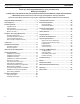
CONTENTS Designer Series Gas Fireplaces Thank you and congratulations on your purchase of a Monessen Fireplace. PLEASE READ THE INSTALLATION AND OPERATION INSTRUCTIONS BEFORE USING THE APPLIANCE! IMPORTANT: Read all instructions and warnings carefully before starting installation. Failure to follow these instructions may result in a possible fire hazard and will void the warranty. Important Safety Information.......................................3 Checking Gas Pressure...................................
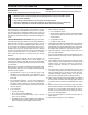
IMPORTANT SAFETY INFORMATION Designer Series Gas Fireplaces OWNER Please leave these instructions with the owner. Please retain these instructions for future reference. WARNING INSTALLER • Read this owner’s manual carefully and completely before trying to assemble, operate, • • or service this fireplace. Any change to this fireplace or its controls can be dangerous.
IMPORTANT SAFETY INFORMATION and code approval 14. Do not use any solid fuels (wood, coal, paper, cardboard, etc.) in this fireplace. Use only the gas type indicated on rating plate. 15. This appliance, when installed, must be electrically grounded in accordance with local codes or in the absence of local codes, with the National Electrical Code, ANSI/NFPA 70, or the Canadian Electrical Code, CSA C22.1. 16. Do not obstruct the flow of combustion and ventilation air in any way.
product features Designer Series Gas Fireplaces product SPECIFICATIONS • This appliance has been certified for use with • • • • • • • either natural or propane gas. See appropriate data plates. This appliance is not for use with solid fuels. The appliance is approved for bedroom or bedsitting room installations. The appliance must be installed in accordance with local codes if any. If none exist use the current installation code. ANSI Z223.1/NFPA 54 in the USA, CSA B149 in Canada.
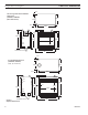
FIREPLACE DIMENSIONS Designer Series Gas Fireplaces 2(6QE” See-Through and Peninsula Model Dimensions (624DVST, 624DVPF) (Rear Vent Shown) 23 6M” 18(6 ” 4(6QE” 39 6 ” C L 405 6QE” 5/8” 1/2” 32 6M” 3456O” 1/2” 5/8” Gas/Electric Access 44” 356M” 420200 6000Dv penin dims Corner Model Dimensions (624DVCR, 624DVCL) (Right, Top Vent Shown) 18(6 ” 2456O” 4(6QE” 39 6 ” 5/8” 1/2” 37 6M” 37 6M” 405 6QE” 1/2” 1 6M” 1956O” 3256M” 5/8” Gas/Electric Access 44” Figure 2 Fireplace Dimensions
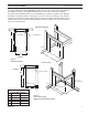
FIREPLACE Framing Designer Series Gas Fireplaces It is best to build firebox framing after the appliance is set in place. Refer to the dimensions for your fireplace on Page 7. The framing headers may rest on the top of the firebox standoffs. The firebox may be installed directly on a combustible floor or raised on a platform of an appropriate height. Do not place firebox on carpeting, vinyl, or other soft floor coverings.
framing FIREPLACE Designer Series Gas Fireplaces Framing See Through Fireplace * Note: For ease of installation, frame around the firebox after it has been set. Refer to chart below for specifications. When installing into existing framed (A1) openings, loosen the junction box. Remove the rear-mounted flue pipe adaptor. Refer to Page 16, Figures 10 and 11. Reattach both assemblies.
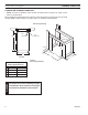
clearances Designer Series Gas Fireplaces WARNING Clearances to combustibles Follow these instructions carefully to ensure safe installation. Failure to follow instructions exactly can create a fire hazard. The appliance cannot be installed on a carpet, tile or other combustible material other than wood flooring. If installed on carpet or vinyl flooring, the appliance shall be installed on a metal, wood or noncombustible material panel extending full width and depth of the appliance.
INSTALLATION INFORMATION Designer Series Gas Fireplaces INSTALLATION AND OPERATING INSTRUCTIONS This gas fireplace should be installed by a qualified installer in accordance with local building codes and with current CSA-B149 (.1 or .2) Installation codes for Gas Burning Fireplaces and Equipment. If the unit is being installed in a mobile home the installation should comply with the current CAN/ CSA Z 240 .4 code. FOR U.S.A. Installations follow local codes and/or the current National Fuel Gas Code.
INSTALLATION Designer Series Gas Fireplaces X X X B A Y Z A A Flat on Wall B Room Divider Y Y FP2277 Figure 7 Possible Fireplace Locations A. WALL LOCATION Y Minimum distance between a glass panel andFP2277 a parallel wall = 42" locate Z Minimum distance between the edge of a glass panelfireplace and an adjacent wall = 3" B. Island Location X (Maximum length of horizontal venting = 20'. Refer to the venting section of this manual for specific dimensions.
OPTIONAL TOP VENT installation Designer Series Gas Fireplaces WARNING Optional top vent application The appliance is shipped as a rear vent unit. If the installation layout requires the unit to be a top vent configuration the appliance can be converted by following the steps below. When removing and refitting the plates and adapter be sure the associated gaskets are undamaged and refitted as required. 1. Remove the eight (8) screws securing the flue pipe adapter to the fireplace body. Figure 9 2.
VENTING INSTALLATION Designer Series Gas Fireplaces NOTICE VENTING CLEARANCES Read all instructions completely and thoroughly before attempting installation. Failure to do so could result in serious injury, property damage or loss of life. Operation of improperly installed and maintained venting system could result in serious injury, property damage or loss of life.
VentING installation installation planning There are two basic types of direct-vent installation: • Horizontal Termination • Vertical Termination WARNING Designer Series Gas Fireplaces Never run the vent pipe down. This may cause excessive temperatures which could cause a fire. It is important to select the proper length of vent pipe for the type of termination you choose. It is also important to note the wall thickness. for horizontal termination Select the amount of vertical rise desired.
ventING installation Designer Series Gas Fireplaces General Venting Information - Termination Location INSIDE CORNER DETAIL G V H A D L V E C B V F Figure 13 Termination Locations B Fixed Closed Ope ra V B B V Fixed Closed Operable B V J A CFM145a V VENT TERMINATION B V ble X AIR SUPPLY INLET X M I V K X AREA WHERE TERMINAL IS NOT PERMITTED Canadian Installations1 US Installations2 CFM145a A = Clearance above grade, veranda, porch, 12” (30 cm)DV Termin Location 12” (30
ventING installation Designer Series Gas Fireplaces termination clearances for buildings with combustible and noncombustible exteriors D C C G G=6" (152mm) V V V Inside Corner E F=6" (152mm) F Outside Corner C = Maximum depth of 48" (1219mm) for alcove location D = Minimum width for back wall of alcove location Combustible - 38" (965mm) Noncombustible - 24" (610mm) E = Clearance from corner in alcove location Combustible - 6" (152mm) Noncombustible - 2" (51mm) H G V V G = Combustible 24"(61
Venting installation Designer Series Gas Fireplaces Rear Wall Vent installation When installed as a rear vent unit this appliance may be vented directly to a termination located on the rear wall behind the appliance • The maximum horizontal distance between the rear of the appliance and the outside face of the • rear wall is 20" (508 m). Figure 16 Only one 45° elbow is allowed in these installations.
ventING installation Designer Series Gas Fireplaces Rear Wall Vent installation (continued) Cut Vinyl Siding Away to Fit Standoff WARNING 4. Apply a bead of non-hardening mastic around the outside edge of vent cap. Position the vent cap in the center of hole on the exterior wall with the word “UP” on the vent cap facing up. Insure proper clearance of 1" to combustibles is maintained. Attach the vent cap with four wood screws supplied.
ventING installation Designer Series Gas Fireplaces Horizontal termination configurations 40 Since it is very important that the venting system maintain its bal- 38 ance between the combustion air intake and the flue gas exhaust, 36 certain limitations as to vent configurations apply and must be strictly 34 adhered to. 32 The Vent Graph, showing the relationship between vertical and horizontal 30 side wall venting, will help to determine the various dimensions allowable.
ventING installation Designer Series Gas Fireplaces horizontal termination configuration (Continued) • If a 90° elbow is used in the horizontal vent run, the horizontal 90° vent length is reduced by 36" (914 mm). Figure 25. This does not apply if the 90° elbows are used to increase or redirect a vertical rise. Figure 25 A B Example: According to the vent graph, Figure 22, the maximum horizontal vent length in a system with a 7.
ventING installation Designer Series Gas Fireplaces Below Grade Installations When it is not possible to meet the required vent terminal clearances of 12" above grade level, a snorkel kit is recommended. It allows installation depth down to 7" (178 mm) below grade level. The 7" (178 mm) is measured from the center of the horizontal vent pipe as it penetrates through the wall. Ensure that sidewall venting clearances are observed.
ventING installation Designer Series Gas Fireplaces vertical through-the-roof applications This Gas Fireplace has been approved for, • Vertical installations up to 40' (12 m) in height. Up to a 10' (3 m) horizontal vent run can be installed within the vent system using a maximum of two 90° elbows.
ventING installation Designer Series Gas Fireplaces installation for vertical termination 1. Determine the route your vertical venting will take. If ceiling joist, roof rafters or other framing will obstruct the venting system, consider an offset. Refer to Figure 32 to avoid cutting load bearing members. NOTE: Pay special attention to these installation instructions for required clearances (air space) to combustibles when passing through ceilings, walls, roofs, enclosures, attic rafters, etc.
Designer Series Gas Fireplaces ventING installation 4. Connect a section of pipe and extend up through the hole. NOTE: If an offset is needed to avoid obstructions, you must support the vent pipe every three (3) feet. Use wall straps for this purpose. Refer to Page 23, Figure 30. Whenever possible, use 45° elbows instead of 90° elbows. The 45° elbow offers less restriction to the flow of the flue gases and intake air. 5. Place the flashing over the pipe section(s) extending through the roof.
fireplace installation Designer Series Gas Fireplaces check gas type Use proper gas type for the fireplace you are installing. If you have conflicting gas type, do not install fireplace. See dealer where you purchased the fireplace for proper fireplace for your gas type or conversion kit. A qualified installer or service person must connect appliance to gas supply. Follow all local codes.
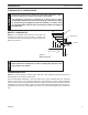
fireplace installation Only persons licensed to work with gas piping may make the necessary gas connections to this appliance. CAUTION WARNING Designer Series Gas Fireplaces A manual shutoff valve must be installed upstream of the appliance. Union tee and plugged 1/8” NPT pressure tapping point should be installed upstream of the appliance. Figure 35 NOTE : The gas line connection may be made using 1/2" rigid tubing or an approved flex connector.
Millivolt & electronic CHECK GAS PRESSURE and Electrical installation Designer Series Gas Fireplaces WARNING 1. Check gas type. The gas supply must be the same as stated on the appliance’s rating decal. If the gas supply is different from the fireplace, STOP! Do not install the appliance. Contact your dealer immediately. 2. To ease installation, a 30" (762 mm) flex line with manual shut-off valve has been provided with on this appliance. Install and attach 1/2" gas line onto shut-off valve. 3.
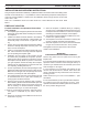
Electrical installation Designer Series Gas Fireplaces Remote Wall mounted Switch A remote wall switch and up to fifteen (15) feet of 18 Ga. wire may be used with this appliance. Attach the wall switch in a junction box at the desired location on the wall. Figure 38. Do not extend beyond the wall switch wire length provided. NOTE: Extended lengths of wire may cause the fireplace not to function properly. Longer length of wire is permitted if the wire is made out of larger gauge (diameter) wire.
Electrical installation WARNING Electronic Pilot Ignition Wiring Designer Series Gas Fireplaces Do not connect 110-120V AC to the Remote Wall Switch. The appliance will malfunction. Figure 39 Remote Wall Switch Wiring Diagram Remote Wall Switch FP2551 remote switch wiring Position the wall switch. Do not extend beyond the 15 feet of wire. Optional DC Remote Systems These instructions replace the section entitled Hearth Mount in the Millivolt hand held remote instructions supplied with the remote. 1.
glass removal Designer Series Gas Fireplaces Glass Frame Removal All three (3) glass frames are replaced the same way. 1. Release two clamps on bottom of fireplace. Figure 40 2. Tilt glass frame out and lift glass frame up until it clears three tabs on top of fireplace. 3. Set glass frame aside. Glass Frame Clamp FP2310 Three Tabs Clamp ! WARNING WARNING Figure 40 Remove Glass Frame Each clamp has a quick spring force. When reinstalling clamps, keep fingers clear.
LOG PLACEMENT Designer Series Gas Fireplaces Before you begin — This unit is supplied with eight ceramic fiber logs. Do not handle these logs with your bare hands. Always wear gloves to prevent skin irritation from ceramic fibers. After handling the logs, wash your hands gently with soap and water to remove any traces of fibers. WARNING The positioning of the logs is critical to the safe and clean operation of this heater.
log placement Designer Series Gas Fireplaces Bottom Center Back Log (#3) 5. Position left end of bottom center back log (#3) beside rear end of left log (#1). Line up pin on grate with pin hole in bottom of center back log (#3) Snug right end of bottom center back log (#3) to the middle of right log (#2). Figure 43 6. Line up pin holes on bottom front log (#4) with pins on grate.
Designer Series Gas Fireplaces log placement Top Log #6 Grate Prong Four Cutout on Bottom Center Log 8. Place Y-Shaped end of top log (#6) on on prong four of back of grate. Position other end of top log (#6) in cutout of bottom center log (#3). Figure 46 Control Panel Figure 46 Install Top Log (#6) L643 DV6000 top log 9. Break up rock wool (ember material) into dime-sized pieces. Place evenly across burner surface and mesh of grate. Figure 47. Do not exceed 1" depth of coverage.
Designer Series Gas Fireplaces AIR RESTRICTOR ADJUSTMENT The fireplace is equipped with a restrictor plate that is located inside the top chamber of the fireplace. Depending upon the vent configuration, you may be required to adjust the restrictor position 1. Remove glass frame. Refer to Glass Frame Removal, Page 31. 2. Using a Phillips screw driver, loosen the screw that secures the air restrictor. Do not back the screw all the way out. 3.
OPERATING INSTRUCTIONS Designer Series Gas Fireplaces WARNING for your safety read before lighting If you do not follow these instruction exactly, a fire or explosion may result causing property damage, personal injury or loss of life. A. This appliance is equipped with a pilot which must be lit with built-in battery ignitor while following these instructions exactly. B. BEFORE OPERATING smell all around the appliance area for gas.
OPERATING INSTRUCTIONS Designer Series Gas Fireplaces approved leak testing method You may check for gas leaks with the following methods only: • Soap and water solution • An approved leak testing spray danger • Electronic sniffer Never check for gas leak with open flame! WARNING Lighting pilot for the first time If using a soap and water solution to test for leaks, DO NOT spray solution onto control body. NOTE: Remove any excessive pipe compound from the connections.
OPERATING INSTRUCTIONS Designer Series Gas Fireplaces Lighting burner OFF RS The “ON/OFF/RS” switch for the main burner can be found behind door of the fireplace. This switch allows you to turn on and to turn off the main burner without using the gas valve knob. Make sure the button is in the “ON” position to light the main burner. Figure 50 ON main burner switch Figure 50 On/Off/RS Switch Lighting the burner OFF ON Depress and turn the knob counterclockwise to the “ON” position. Figure 51.
cleaning and maintenance Designer Series Gas Fireplaces Make sure the gas valve knob is in the “OFF” position. Wait at least five (5) minutes before start ing maintenance. Fireplace must be cold before starting maintenance. CAUTION Venting system A qualified agency should examine the venting system annually. Cleaning glass Allow glass to cool before cleaning. Do not clean glass when it is hot. Damage could occur. Clean the tempered glass periodically.
Designer Series Gas Fireplaces troubleshooting Standing Pilot Ignition SYMPTOM POSSIBLE CAUSE ACTION 1. Spark ignitor will A. Wire disconnected. not light pilot after repeated triggering of B. Defective ignitor. piezo. C. No gas or low gas pressure. D. No Propane/LPG in tank 2. Pilot will not stay lit A. Defective thermocouple after carefully following lighting instructions. B. Defective valve 3. Pilot burning, valve A.
troubleshooting Designer Series Gas Fireplaces electronic Ignition START 1. Turn gas supply off. 2. Turn ON/OFF switch to “ON” Power to module (24V Normal) NO YES Is there a spark across ignitor sensor gap? NO Check: Line voltage (120VAC) Low voltage transformer (19.5 minimum VAC) ON/OFF switch Wiring connections Unplug ignition lead and check spark at module (24VAC normal). Is spark OK? NO Replace module YES A. Check ignition cable ground wiring, ceramic insulator and gap. Correct if necessary.
troubleshooting Designer Series Gas Fireplaces General troubleshooting SYMPTOM POSSIBLE CAUSE ACTION 6. Glass Soots A. Flame impingement on logs A. Install log set per the instructions Inspect the injector and air intake area. Make sure this area does not have any blockage from debris and clean. Check gas supply. 7. Flame burn blue and lifts off burner (ghosting) A. Insufficient oxygen being supplied A. Ensure that the vent cap is installed properly and free of debris.
replacement parts Designer Series Gas Fireplaces LOGS 2 1 3 4 5 WARNING 6 LG646 DV6000 log parts Ref. Description Qty 1. Left Bottom Log, #1 1 2. Right Bottom Log, #2 1 3. Bottom Center Log, #3 1 4. Bottom Front Log, #4 1 5. Left Top Log, #5 1 6. Top Log, #6 1 42 Failure to position the parts in accordance with these diagrams or failure to use only parts specifically approved with this appliance may result in property damage or personal injury.
replacement parts Designer Series Gas Fireplaces REPLACEMENT PARTS ARE AVAILABLE THROUGH YOUR RETAILER 5 6 4 7 3 *2 (2-Peninsula 2-See-through 1-Corner) WARNING 1 Failure to position the parts in accordance with these diagrams or failure to use only parts specifically approved with this appliance may result in property damage or personal injury. 420200 DV6000 firebox parts Ref. Description Qty 1. Junction Box 1 2. Large Glass Assy 1* (Peninsula, See-through) 2.
REPLACEMENT PARTS Designer Series Gas Fireplaces Standing Pilot – Millivolt Control 2I 2C 1 3 2T 2 5 4 6 7 8 9,10,11,12 Fuel Conversion Kits - Millivolt Natural Gas to LP 300 Conversion LP to Natural Gas 300 Conversion 44 Kit #6000CKP Kit #6000CKN WARNING Ref. Description Qty 1. Gas Valve Assy 1 2. Pilot Assy 1 2C. Replacement Thermocouple 1 2I. Replacement Igniter and Wire 1 2T. Replacement Thermopile 1 3. Flexhose w/ Shut-off Valve 1 4. Rocker Switch 1 420200 5. Piezo Igniter 1 DV6000 6.
REPLACEMENT PARTS Designer Series Gas Fireplaces ELECTRONIC IGNITION 1 3 2 LO HI 5 4 6 7 9 8 Ref. Description Qty 1. Gas Valve Assy 1 2. Pilot Assy 1 3. Flexhose w/ Shut-off Valve 1 4. Rocker Switch 1 5. Injector 1 6. Burner Assy 1 7. Wire Assy 1 8. Ignition Module 1 9.
REPLACEMENT PARTS Designer Series Gas Fireplaces Vent Components 1 7 4 8 9 HO T 5 2 3 6 11 10 Ref. Qty/Box 1. 1 1. 1 1. 1 2. 1 3. 6 3. 6 3. 6 3. 6 3. 6 3. 6 4. 6 4. 6 5. 6 5. 6 6. 6 6. 6 7. 6 8. 6 9. 6 10. 1 11. 1 46 Simpson Durvent Description or MHSC Pt. No.
Designer Series Gas Fireplaces 42D0200 47
Designer Series Gas Fireplaces 48 42D0200
Designer Series Gas Fireplaces 42D0200 49
Designer Series Gas Fireplaces Massachusetts Residents Only — Please read and follow these special requirements NOTE REGARDING VENTED PRODUCTS This product must be installed by a licensed plumber or gas fitter when installed within the Commonwealth of Massachusetts. Any residence with a direct vent product must have a CO detector installed in the residence.
Designer Series Gas Fireplaces Limited lifetime warranty policy Lifetime Warranty The following components are warranted for life to the original owner, subject to proof of purchase: Firebox, Combustion Chamber, Heat Exchanger, Grate and Stainless Steel Burners. Five Year Warranty The following components are warranted five (5) years to the original owner, subject of proof of purchase: Ceramic Fiber Logs.
Based on CSA P.4.1-09 Efficiency Ratings Model 624DVSTNVC 624DVPFNVC 624DVCRNVC 624DVCLNVC 624DVSTPVC 624DVPFPVC 624DVCRPVC 624DVCLPVC 624DVSTNEC 624DVPFNEC 624DVCRNEC 624DVCLNEC 624DVSTPEC 624DVPFPEC 624DVCRPEC 624DVCLPEC EnerGuide Ratings Fireplace Efficiency (%) 62.8 62.8 62.8 62.8 70.6 70.6 70.6 70.6 65.1 65.1 65.1 65.1 73.4 73.4 73.4 73.4 MHSC 149 Cleveland Drive • Paris, Kentucky 40361 www.mhsc.