B-Vent Series Natural Vent Gas Fireplace Installation & Operating Instructions Models: BBV400, SBV400, SBV500 WARNING IF THE INFORMATION IN THESE INSTRUCTIONS IS NOT FOLLOWED EXACTLY, A FIRE OR EXPLOSION MAY RESULT CAUSING PROPERTY DAMAGE, PERSONAL INJURY OR LOSS OF LIFE. — Do not store or use gasoline or other flammable vapors and liquids in the vicinity of this or any other appliance. — WHAT TO DO IF YOU SMELL GAS • Do not try to light any appliance.
BBV, SBV Series Natural Vent Gas Fireplaces TABLE OF CONTENTS Thank you and congratulations on your purchase of an MHSC Fireplace Please read the Installation and Operation Instructions before using the appliance! IMPORTANT: Read all instructions and warnings carefully before starting installation. Failure to follow these instructions may result in a possible fire hazard and will void the warranty. Important Safety Information............................3 Code Approval....................................
BBV, SBV Series Natural Vent Gas Fireplaces IMPORTANT SAFETY INFORMATION OWNER Please leave these instructions with the appliance. Please retain these instructions for future reference. WARNING INSTALLER • Read this owner’s manual carefully and completely before trying to assemble, operate, or service this fireplace. Any change to this fireplace or its controls can be dangerous.
BBV, SBV Series Natural Vent Gas Fireplaces IMPORTANT SAFETY INFORMATION Continued on Page 4 WARNING IMPORTANT: PLEASE READ THE FOLLOWING CAREFULLY It is not unusual for gas fireplace to give off some odor the first time it is burned. This is due to the manufacturing process. Please ensure that your room is well ventilated during burn off - open all windows. It is recommended that you burn your fireplace for at least en (10) hours the first time you use it.
BBV, SBV Series Natural Vent Gas Fireplaces PRODUCT FEATURES PRODUCT SPECIFICATIONS GAS pressures • This appliance has been certified for use with either • • • • natural or propane gas. See appropriate data plates. This appliance is not for use with solid fuels. The appliance must be installed in accordance with local codes if any. If none exist use the current installation code, ANSI Z223.1/NFPA 54 in the US and CSA B149 in Canada. The appliance must be properly connected to a venting system.
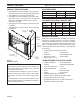
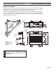
FIREPLACE DIMENSIONS & FRAMING BBV, SBV Series Natural Vent Gas Fireplaces FIREPLACE FRAMING Firebox framing can be built before or after the appliance is set in place. Construct firebox framing following Figures 2 or 3 for your specific installation requirements. Refer to Figures 2 & 3 for firebox dimensions. The framing headers may rest on the top of the firebox standoffs. The firebox may be installed directly on a combustible floor or raised on a platform of an appropriate height.
BBV, SBV Series Natural Vent Gas Fireplaces FIREPLACE DIMENSIONS & FRAMING Min. Rough Opening Depth G C 4” B-Vent 21” (533 mm) F 2156O” (546 mm) G 1/2” or 5/8” Drywall Spacers 13(6QE” 656O” (341 mm) (165 mm) E D - Min. Rough Opening Width 1/2" or 5/8" Drywall Spacers Min.
PRE-INSTALLATION INFORMATION BBV, SBV Series Natural Vent Gas Fireplaces FIREPLACE LOCATION Plan for the installation of your appliance. This includes determining where the unit is to be installed, the vent configuration to be used, framing and finishing details, and whether any optional accessories (i.e. wall switch, or remote control) are desired. Consult your local building code agency to ensure compliance with local codes, including permits and inspections.
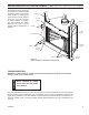
SECURE FIREPLACE TO FLOOR OR FRAMING The fireplace must be secured to the floor and/or to framing studs as shown in Figure 5. Use two (2) wood screws or masonry/concrete screws to secure fireplace to the floor. Use four (4) screws to attach fireplace to framing. The side brackets are adjustable from 1/2” to 5/8” to accommodate different thicknesses of material.
NOTICE WARNING BBV, SBV Series Natural Vent Gas Fireplaces Read all instructions completely and thoroughly before attempting installation. Failure to do so could result in serious injury, property damage or loss of life. Operation of improperly installed and maintained venting system could result in serious injury, property damage or loss of life. Failure to follow these instructions will void the warranty. INSTALLATION PRECAUTIONS Consult local building codes before beginning the installation.
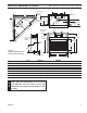
VENT INSTALLATION BBV, SBV Series Natural Vent Gas Fireplaces FIRESTOPS • Locate chimney centerline dimension from a com- • bustible back wall. Figures 2 & 3. Minimum firestop dimensions are found in the vent manufacturer’s instructions. Clearances to combustibles may also be found on the sides of the flue sections. Avoid cutting any load-bearing framing members. Figures 6 & 7 To position firestop refer to Figures 6 & 7. Only one firestop is required per frame.
BBV, SBV Series Natural Vent Gas Fireplaces NOTE: The use of outside air for combustion is optional unless required by building codes. It is only necessary to supply outside combustion air to one side of fireplace. Use model OAC4 combustion air kit (refer to Page 17). 1. Avoid extremely long runs and numerous turns in duct leading from fireplace to combustion air assembly. These conditions increase the resistance to free flow of air through duct. Figures 9 and 10 2.
BBV, SBV Series Natural Vent Gas Fireplaces 1. Remove the cover plate from the 4” outlet opening location on the left outside of the fireplace. 2. Place starting collar (4”) into hole on left side of fireplace. Fireplace shortest side of air starting collar through fireplace outer wrap. Fasten starting collar in place with four (4) sheet metal screws provided. Figure 11 NOTE: The air starting collar extends through the fireplace outer wrap.
BBV, SBV Series Natural Vent Gas Fireplaces FIREPLACE INSTALLATION CHECK GAS TYPE Use proper gas type for the fireplace you are installing. If you have conflicting gas types, do not install fireplace. See dealer where you purchased the fireplace for proper fireplace for your gas type.
BBV, SBV Series Natural Vent Gas Fireplaces CAUTION WARNING FIREPLACE INSTALLATION Only persons licensed to work with gas piping may make the necessary gas connections to this appliance. A manual shut-off valve must be installed upstream of the appliance. Union tee and plugged 1/8” NPT pressure tapping point should be installed upstream of the appliance. Figure 17 NOTE: The gas line connection may be made using 1/2” rigid tubing or an approved flex connector.
BBV, SBV Series Natural Vent Gas Fireplaces CHECKING GAS PRESSURE 1. Check gas type. The gas supply must be the same as stated on the appliance’s rating decal. If the gas supply is different from the fireplace, STOP! Do not install the appliance. Contact your dealer immediately. 2. To ease installation, a 30” (762 mm) flex line with manual shut-off valve has been provided with this appliance. Install and attach 1/2” gas line onto shut-off valve. 3.
BBV, SBV Series Natural Vent Gas Fireplaces ELECTRICAL INSTALLATION WARNING Electrical connections should only be performed by a qualified, licensed electrician. Main power must be off when connecting to main electrical power supply or performing service. All wiring shall be in compliance with all local, city and state codes.
BBV, SBV Series Natural Vent Gas Fireplaces ELECTRICAL INSTALLATION WARNING ELECTRONIC PILOT IGNITION WIRING Do not connect 110-120V AC to the Remote Wall Switch. The appliance will malfunction or destroyed. Figure 17 Electronic Ignition System Wiring Diagram FP2027 &0 ELECTRONIC IGNITION WIRING Position the wall switch. Do not extend beyond the 15’ of wire.
FINAL INSTALLATION BBV, SBV Series Natural Vent Gas Fireplaces ROCK WOOL PLACEMENT Cover with Rock Wool 1. Place rock wool on burner to provide glowing embers. For best results, pull the rock wool apart into pieces the size of a nickel or dime. Burner 2. Distribute one layer of rock wool to cover the entire burner. Figure 18 3. Place the logs on the burner. Refer to Log Placement Section. WARNING If the flame is blue and only in the center, turn off unit and allow to cool.
BBV, SBV Series Natural Vent Gas Fireplaces OPERATING INSTRUCTIONS WARNING FOR YOUR SAFETY READ BEFORE LIGHTING If you do not follow these instructions exactly, a fire or explosion may result causing property damage, personal injury or loss of life. A. This appliance is equipped with a pilot which must be lit with an ignitor while following these instructions exactly. B. BEFORE OPERATING smell all around the appliance area for gas.
OPERATING INSTRUCTIONS BBV, SBV Series Natural Vent Gas Fireplaces APPROVED LEAK TESTING METHOD You may check for gas leaks with the following methods only: DANGER • Soap and water solution • An approved leak testing spray • Electronic sniffer WARNING LIGHTING PILOT FOR THE FIRST TIME If using a soap and water solution to test for leaks, DO NOT spray solution onto control body. NOTE: Remove any excessive pipe compound from the connections. Excessive pipe compound can set off electronic sniffers.
BBV, SBV Series Natural Vent Gas Fireplaces OPERATING INSTRUCTIONS LIGHTING BURNER LIGHTING THE BURNER Depress and turn the knob counterclockwise to the “ON” position. Figure 22. It will take less than four (4) seconds for the burner to ignite. PILOT POSITION Figure 21 On/Off/RS Switch &0 ROCKER SWITCH OFF ON Depress and turn knob to pilot position to keep burner off while maintaining the pilot light.
OPERATING INSTRUCTIONS BBV, SBV Series Natural Vent Gas Fireplaces WARNING FOR YOUR SAFETY READ BEFORE LIGHTING If you do not follow these instructions exactly, a fire or explosion may result causing property damage, personal injury or loss of life. A. This appliance is equipped with an ignition device (Piezo) which automatically lights the pilot. Do NOT try to light the burner by hand. B. BEFORE OPERATING smell all around the appliance area for gas.
CLEANING and MAINTENANCE WARNING BBV, SBV Series Natural Vent Gas Fireplaces Turn off gas before servicing fireplace. It is recommended that a qualified service technician perform these check-ups at the beginning of each heating season. BURNER, PILOT AND CONTROL COMPARTMENT Thermocouple Thermopile Keep the control compartment, logs and burner areas surrounding the logs clean by vacuuming or brushing at least twice a year.
CLEANING and MAINTENANCE BBV, SBV Series Natural Vent Gas Fireplaces VENT SYSTEM The fireplace and venting system should be inspected before initial use and at least annually by a qualified field service person. Inspect the external vent cap on a regular basis to make sure that no debris is interfering with the airflow. Inspect entire venting system to ensure proper function. LOGS Leave logs installed in the fireplace for cleaning. Vacuum surface of the logs with a brush attachment.
BBV, SBV Series Natural Vent Gas Fireplaces REPLACEMENT PARTS FIREBOX COMPONENTS 1 6 2 4a 4b 3 4c 5 7 26 ""6 3"6 FIREBOX PARTS 62D4036
BBV, SBV Series Natural Vent Gas Fireplaces REPLACEMENT PARTS FIREBOX COMPONENTS Item Description 1. Pull Screen Panel 2. Refractory Side 3. Refractory Back 4a. Left Refractory 4b. Middle Refractory 4c. Right Refractory Optional Field Installed Accessoriesd 5. Firebrick Assembly 6. Outside Air Kit 7. Black Glass Door Assembly 7. Polished Brass Glass Door Assembly 7. Stainless Glass Door Assembly Qty.
BBV, SBV Series Natural Vent Gas Fireplaces REPLACEMENT PARTS STANDING PILOT - MILLIVOLT CONTROL 2C 1 2I 2T 2 5 6 3 4 7 9 8 11 12, 13 10 ""6 3"6 CONTR PARTS 28 62D4036
REPLACEMENT PARTS BBV, SBV Series Natural Vent Gas Fireplaces STANDING PILOT - MILLIVOLT CONTROL Item Description Qty. BBV400NV BBV400PV SBV400NV SBV400PV SBV500NV SBV500PV 1. Gas Valve Assembly 1 37D0117 37D0118 37D0117 37D0118 37D0117 37D0118 2. Pilot Assembly 1 37D0018 37D0019 37D0018 37D0019 37D0018 37D0019 2C. Replacement Thermocouple 1 37D1067 37D1067 37D1067 37D1067 37D1067 37D1067 2I. Replacement Igniter and Wire 1 37D1069 37D1069 37D1069 37D1069 37D1069 37D1069 2T.
BBV, SBV Series Natural Vent Gas Fireplaces REPLACEMENT PARTS ELECTRONIC IGNITION 1 2 5 3 4 6 8 7 11 12 9 10 ""6 3"6 ELECTRONIC IGNITION PARTS 30 62D4036
REPLACEMENT PARTS BBV, SBV Series Natural Vent Gas Fireplaces ELECTRONIC IGNITION Item 1. 2. 3. 4. 5. 6. 7. 8. 9. 10. 11. 12. Description Qty.
BBV, SBV Series Natural Vent Gas Fireplaces TROUBLESHOOTING STANDING PILOT IGNITION SYMPTOM 1. Spark igniter will not light pilot after repeated triggering of piezo. POSSIBLE CAUSE A. Wire disonnected. B. Defective igniter. C. No gas or low gas pressure. D. No Propane/LPG in tank. 2. Pilot will not stay lit after carefully following lighting instructions. A. Defective thermocouple. B. Defective valve. 3.
TROUBLESHOOTING BBV, SBV Series Natural Vent Gas Fireplaces ELECTRONIC IGNITION START 1. Turn gas supply off. 2. Turn ON/OFF switch to “ON” Power to module (24V Normal) NO YES Is there a spark across ignitor sensor gap? NO Check: Line voltage (120VAC) Low voltage transformer (19.5 minimum VAC) ON/OFF switch Wiring connections Unplug ignition lead and check spark at module (24VAC normal). Is spark OK? NO Replace module YES YES A. Check ignition cable ground wiring, ceramic insulator and gap.
BBV, SBV Series Natural Vent Gas Fireplaces TROUBLESHOOTING GENERAL TROUBLESHOOTING SYMPTOM POSSIBLE CAUSE ACTION 1. Glass soots. A. Flame impingement on logs. A. Install log set per instructions. Inspect the injector and air intake area. Make sure this area does not have any blockage from debris and clean. Check gas supply. 2. Poor draft due to venting. A. Too much offset. A. Reduce offset and/or raise termination. If thermocouple is producing more than 15m B, replace faulty valve. B.
BBV, SBV Series Natural Vent Gas Fireplaces 62D4036 35
BBV, SBV Series Natural Vent Gas Fireplaces 36 62D4036
BBV, SBV Series Natural Vent Gas Fireplaces 62D4036 37
Massachusetts Residents Only — Please read and follow these special requirements BBV, SBV Series Natural Vent Gas Fireplaces NOTE REGARDING VENTED PRODUCTS This product must be installed by a licensed plumber or gas fitter when installed within the Commonwealth of Massachusetts. Any residence with a direct vent product must have a CO detector installed in the residence.
BBV, SBV Series Natural Vent Gas Fireplaces LIMITED LIFETIME WARRANTY POLICY LIFETIME WARRANTY The following components are warranted for life to the original owner, subject to proof of purchase; Firebox, Combustion Chamber, Heat Exchanger, Grate and Stainless Steel Burners. FIVE YEAR WARRANTY The following components are warranted for five (5) years to the original owner, subject to proof of purchase; Ceramic Fiber Logs.
MHSC 149 Cleveland Drive • Paris, Kentucky 40361 www.mhsc.