UNVENTED GAS CAST IRON STOVE INSTALLATION AND OPERATING INSTRUCTIONS �� � �� MODELS: C2801VF, C2802VF, C2803VF, and C2804VF Natural Gas or Propane/LPG Milli-Volt Control WARNINGS WARNINGS If the information in this manual is not followed exactly, a fire or explosion may result causing property damage, personal injury or loss of life. This appliance may be installed in an aftermarket, permanently located, manufactured (mobile) home, where not prohibited by local codes.
CONTENTS Important Safety Information .............................. 3 Product Features ................................................ 5 Getting Started ................................................... 6 Product Specifications ........................................ 7 Ignition Controls............................................ 7 Pilot............................................................... 7 Thermal Generator ....................................... 7 Log Placement ...........................
IMPORTANT SAFETY INFORMATION INSTALLER Please leave these instructions with the owner. OWNER Please retain these instructions for future reference. IMPORTANT WARNING Read these instructions carefully before installing or trying to operate this vent-free gas heater. • Any change to this heater or its controls can be dangerous. • Improper installation or use of the heater can cause serious injury or death from fire, burns, explosion or carbon monoxide poisoning.
IMPORTANT SAFETY INFORMATION Continued from page 3 15. This is an unvented gas-fired heater. It uses air (oxygen) from the room in which it is installed. Provisions for adequate combustion and ventilation air must be provided. See page 8. 16. Keep room area clear and free from combustible materials, gasoline and other flammable vapors and liquids. 24. Never burn solid fuels in an unvented room heater, fireplace or stove. 25. Do not set kettles or humidifying devices on top of stove. 26.
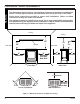
PRODUCT FEATURES On/Off Switch � � �� � Optional Remote Receiver Off/Pilot/On Knob Data and Instruction Plates Optional Thermostat Sensor Hi/Lo Knob Door Figure 1 - Cast Iron Stove 45D0080 5
GETTING STARTED MAKE SURE YOU HAVE RECEIVED ALL PARTS: Check your packing list to verify that all listed parts have been received. You should have the following: • Cast Iron Stove with Burner Assembly • Installation/Operating Instructions • Ceramic fiber logs • Four (4) Leg Levelers • Touch-up Paint Millivolt controlled heater designed to be operated with optional devices for ON/OFF functions.
PRODUCT SPECIFICATIONS NATURAL GAS NOTE: An external regulator is required to reduce supply pressure to a maximum of 101/2" w.c. on Natural Gas systems operating at higher pressure. MILLIVOLT PRESSURE Regulator Pressure Setting: Pilot Regulator: Gas Inlet Pressure: 3.5" w.c. 3.5" w.c. Max. 10 1/2" w. c. Model Number Min. 5" w.c. Type C2801/02/03/04VFN Milli-Volt Gas Rate Max. BTU/Hr Min.
WARNING GENERAL INSTALLATION INFORMATION Do not install the heater … • Where curtains, furniture, clothing, or other flammable objects are less than 42" from the front of the heater. • In high traffic areas. • In windy or drafty areas. CODES Adhere to all local codes or, in their absence, the latest edition of THE NATIONAL FUEL GAS CODE ANSI Z223.1 or NFPA54 which can be obtained from… American National Standards Institute, Inc.
GENERAL INSTALLATION INFORMATION Counter Cast Iron Stove � � Figure 2 - Example of a Large Room with 1/2 Wall Divider The following formula can be used to determine the maximum heater rating per the definition of unconfined space: BTU/Hr = (L1 + L2) Ft x (W) Ft x (H) Ft x 1000 50 Consider two connecting rooms with an open area between, with the following dimensions: L1 = 151/2 Ft., L2 = 12 Ft., W = 12 Ft., H = 8 Ft.
WARNING CLEARANCES / HEIGHT REQUIRMENTS The dimensions shown in Figure 3 are minimum clearances to maintain in installing this heater. Left and right clearances are determined when facing the front of the heater. Follow these instructions carefully to ensure safe installation. Failure to follow instructions exactly can create a fire hazard.
CONNECTING THE GAS CAUTION NOTICE: A qualified gas appliance installer must connect the heater to the gas supply. Consult all local codes. Use new black iron or steel pipe. Internally tinned copper or copper tubing can be used per National Fuel Code, section 2.6.3, providing gas meets hydrogen sulfide limits, and where permitted by local codes. Gas piping system must be sized to provide minimum inlet pressure (Listed on Data Plate) at the maximum flow rate (BTU/Hr).
WARNING CHECKING GAS PRESSURE AND CONNECTING REMOTE RECEIVER Connecting directly to an unregulated propane/L.P.G. tank can cause an explosion. The heater gas inlet connection is 3/8" NPT at the valve. The inlet is located on left side of stove. Remove front control plate to better access the inlet. When tightening up the joint to the valve, hold the valve securely with a wrench to prevent movement.
ELECTRICAL WIRING (MILLI-VOLT) The milli-volt valve is a self-powered combination gas control THAT DOES NOT REQUIRE 110 VAC TO OPERATE. CAUTION ODS Pilot Label all wires prior to disconnection when servicing controls. Wiring errors can cause improper and dangerous operation. Verify proper operation after servicing.
ELECTRICAL WIRING (MILLI-VOLT) INSTALLING THERMOSTAT SENSOR (OPTION SOLD SEPARATELY) 1. 2. 3. Remove the face plate by removing the six screws holding the faceplate in place. This will allow you to pull the faceplate away from the unit about 3" to 4". See Figure 8. �� �� �� �� � Slip the t-stat sensor behind the faceplate. Attach the t-stat sensor to the faceplate with 2 screws provided. Make sure the thermo bulb wire is on the bottom of the t-stat sensor. See Figure 9.
ELECTRICAL WIRING (MILLI-VOLT) 4. Remove adhesive backing from plastic clip. Press clip to bottom of valve. Clip thermo bulb into plastic clip. See Figure 10. 5. Reattach faceplate or reinstall base. 6. Install knob to shaft of t-stat sensor. See Figure 9, page 14. Valve Thermo Bulb Plastic Clip Figure 10 - Clipping Thermo Bulb into Plastic Clip. OPERATION OF THERMOSTAT SENSOR 1. Follow millivolt lighting instructions on lighting plate attached to unit or in homeowner’s manual. 2.
LOG PLACEMENT Before you begin — This unit is supplied with four ceramic fiber logs. Do not handle these logs with your bare hands. Always wear gloves to prevent skin irritation from ceramic fibers. After handling the logs, wash your hands gently with soap and water to remove any traces of fibers. WARNING The positioning of the logs are critical to the safe and clean operation of this heater. Sooting and other problems may result if the logs are not properly and firmly positioned in the appliance.
FLAME APPEARANCE Flames from the pilot, front and rear burner should be visually checked as soon as the heater is installed. In addition, periodically check the flames visually during operation. CHECKING PILOT FLAME The pilot flame must always be present when the heater is in operation. It should just touch the top of the thermocouple tip for natural. See Figure 13 for correct pilot flame. If the pilot flame does not touch the thermocouple, then the burners cannot function reliably.
OPERATING INSTRUCTIONS WARNING FOR YOUR SAFETY READ BEFORE LIGHTING If you do not follow these instruction exactly, a fire or explosion may result causing property damage, personal injury or loss of life. A. This appliance is equipped with an ignition device which automatically lights the pilot. If the piezo is not working properly, see “Match Lighting Instructions,” page 21. B. BEFORE OPERATING smell all around the appliance area for gas.
OPERATING INSTRUCTIONS MILLI-VOLT CONTROL LIGHTING INSTRUCTIONS 1. STOP! Read the safety information label. 2. Make sure the manual shutoff valve is fully open. 3. This gas log set is equipped with an ignition device (piezo) which automatically lights the pilot. If piezo ignitor does not light the pilot, refer to instructions for “Match Lighting Instructions”, page 21. 4. Turn gas control knob clockwise to the OFF position, set the thermostat to the lowest setting and turn ON/OFF switch to OFF position.
OPERATING INSTRUCTIONS AND CLEANING AND SERVICING MATCH LIGHTING INSTRUCTIONS 1. Open stove door. Remove any items necessary for easy access to the pilot (for example: logs, screens, etc.). 2. Follow appropriate lighting instructions found previously. Light a match and hold the flame to the end of the pilot and ignite the pilot. 3. After control knob has been released and pilot stays lit, reinstall any items that were removed for pilot access. Close and latch stove door. 4. Replace ignitor batter.
REPLACEMENT PARTS LIST REPLACEMENT PARTS ARE AVAILABLE THROUGH YOUR RETAILER. LOGS � Item Description Qty 1 Back Log 1 44D1011K 2 Middle Log 1 45D0502K 3 Front Log 1 44D1012K 4 Top Log 1 44D1013K � � WARNING � Failure to position the parts in accordance with these diagrams or failure to use only parts specifically approved with this appliance may result in property damage or personal injury.
REPLACEMENT PARTS BURNER ASSEMBLY � � � � � � � � �� �� ������� WARNING �� �� � 22 Failure to position the parts in accordance with these diagrams or failure to use only parts specifically approved with this appliance may result in property damage or personal injury.
REPLACEMENT PARTS LIST REPLACEMENT PARTS ARE AVAILABLE THROUGH YOUR RETAILER.
WARNING WARNING TROUBLESHOOTING Turn appliance OFF and allow to cool before servicing. Only a qualified service person should service and repair the heater. Note: All troubleshooting items are listed in order of operation. OBSERVED PROBLEM POSSIBLE CAUSE REMEDY When ignitor button is pressed, there is no spark at ODS/pilot. 1. Ignitor electrode positioned wrong. 2. Ignitor electrode is broken. 3. Ignitor electrode not connected to ignitor cable. 4. Ignitor cable pinched or wet. Keep ignitor cable dry.
WARNING TROUBLESHOOTING If the gas quality is bad, your pilot may not stay lit, the burners may produce soot and the heater may backfire when lit. If the gas quality or pressure is low, contact your local gas supplier immediately. OBSERVED PROBLEM POSSIBLE CAUSE REMEDY ODS/pilot lights, but flame goes out when control knob is released. 1. Control knob not fully pressed in. 2. Control knob not pressed in long enough. 6. Thermocouple damaged. 7. Control valve damaged. 1. Press in control knob fully.
NOTES 26 45D0080
NOTES 45D0080 27
LEXINGTON FORGE LIMITED LIFETIME WARRANTY POLICY LIFETIME WARRANTY The following components are warranted for life to the original owner, subject to proof of purchase: Firebox, Combustion Chamber, Heat Exchanger, Grate and Stainless Steel Burners. FIVE YEAR WARRANTY The following components are warranted for 5 years to the original owner, subject of proof of purchase: Ceramic Fiber Logs, Catalytic Filter and Aluminized Burners.