
Stove User Manual


58D6056
19
CSDV Series Direct Vent Gas Stove
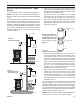
Drop a plumb line from the inside of the roof to the locat-
ing hole in the ceiling. Mark the center point where the
vent will penetrate the roof. Drill a small locating hole
at this point.
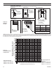
1. Cut a 9Z\x" (241 mm) square hole in the ceiling using the
locating hole as a center point The opening should be
framed to 9Z\x" x 9Z\x" (241 x 241 mm) inside dimensions
as shown in Figure 26 using framing lumber the same
size as the ceiling joist. If the area above the ceiling is
an insulated ceiling or a room, nail firestop from the top
side. This prevents loose insulation from falling into the
required clearance space. Figure 23. Otherwise, install
firestop below the framed hole. The firestop should be
installed with no less than three nails per side. Figure
26
FP1969
firestop w room above
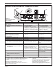
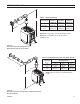
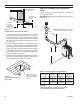
Figure 25 -
If area above is a room, install firestop above framed
hole as shown
Firestop
Nails
FP1969
FP1970
firestop no room
9
56O
"
9
56O"
Figure 26 -
If area above is not a room, install firestop below
framed hole as shown
Nails
Firestop
FP1970
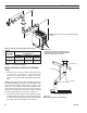
2. Assemble the desired lengths of pipe and elbows nec-
essary to reach from the burner system flue up through
the firestop. Be sure pipe and elbow connections are
fully twist-locked. Page 15, Figure 16
3. Cut a hole in the roof using the locating hole as a center
point. (Cover any exposed open vent pipes before cut-
ting hole in roof). The 9Z\x" x 9Z\x" (241 x 241 mm) hole
must be measured on the horizontal. Actual length may
be larger depending on the pitch of the roof. There
must be a 1" minimum clearance from the vent pipe to
combustible materials. Frame the opening as shown in
on Page 16, Figure 17.
4. Connect a section of pipe and extend up through the
hole.
If an offset is needed to avoid obstructions, you
must support the vent pipe every three (3) feet. Use wall
straps for this purpose. Page 18, Figure 24. Whenever
possible, use 45° elbows instead of 90° elbows. The 45°
elbow offers less restriction to the flow of the flue gases
and intake air.
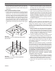
5. Place the flashing over the pipe section(s) extending
through the roof. Secure the base of the flashing to
the roof and framing with roofing nails. Be sure roofing
material overlaps the top edge of the flashing as shown
in Page 18, Figure 24. There must be a 1" clearance
from the vent pipe to combustible materials.
6. Continue to add pipe sections until the height of the vent
cap meets the minimum building code requirements.
You must increase vent height for steep roof
pitches. Nearby trees, adjoining roof lines, steep pitched
roofs, and other similar factors may cause poor draft or
down-drafting in high winds. Increasing the vent height
may solve this problem.
If the vent pipe passes through any occupied areas
above the first floor, including storage spaces and closets,
you must enclose pipe. You may frame and sheetrock the
enclosure with standard construction material. Make sure
to meet the minimum allowable clearances to combustibles.
Do not fill any of the required air spaces with insulation.
1. Remove shingles or other roof covering as necessary
to cut the rectangular hole for the support box. Mark the
outline of the cathedral ceiling support box on the roof
sheathing using the locating hole as a center point.
2. Cut the hole 1/8" larger than the support box outline.
Figure 27.