UNVENTED GAS LOG HEATER OR VENTED DECORATIVE APPLIANCE INSTALLATION AND OPERATING INSTRUCTIONS MODELS DLX18 DLX24 DLX28 Natural Gas or Propane/LPG Control Type: Manual, Thermostat or Milli-Volt WARNINGS If the information in this manual is not followed exactly, a fire or explosion may result causing property damage, personal injury or loss of life. This appliance may be installed in an aftermarket, permanently located, manufactured (mobile) home, where not prohibited by local codes.
CONTENTS Important Safety Information .......................... 3 Electrical Wiring (Milli-volt) ........................... 21 Getting Started ................................................. 5 Log Placement ............................................... 23 Product Features and Specifications ............. 6 Flame Appearance ......................................... 24 General Installation Information .................... 7 Checking the Burner Flame ..........................
IMPORTANT SAFETY INFORMATION INSTALLER Please leave these instructions with the appliance. OWNER Please retain these instructions for future reference. IMPORTANT WARNING Read these instructions carefully before installing or trying to operate this vent-free gas heater. • Any change to this heater or its controls can be dangerous. • Improper installation or use of the heater can cause serious injury or death from fire, burns, explosion or carbon monoxide poisoning.
IMPORTANT SAFETY INFORMATION Continued from page 3 18. During manufacturing, fabricating and shipping, various components of this appliance are treated with certain oils, films or bonding agents. These chemicals are not harmful but may produce annoying smoke and smells as they are burned off during the initial operation of the appliance; possibly causing headaches or eye or lung irritation. This is a normal and temporary occurrence.
GETTING STARTED MAKE SURE YOU HAVE RECEIVED ALL PARTS: Check your packing list to verify that all listed parts have been received. You should have the following: • Unvented gas log grate/burner assembly. • Installation/operating instructions. • Ceramic fiber logs. • Two (2) anchoring screws. • Plastic bag containing crushed volcanic rock. The millivolt controlled version of this heater is the only style designed to be operated with optional devices for ON/OFF functions.
PRODUCT FEATURES AND SPECIFICATIONS NATURAL GAS Note: An external regulator is required to reduce supply pressure to a maximum of 101/2 W.C. (11" W.C. for HI/LO) on natural gas systems operating at higher pressure. MANUAL / T-STAT PRESSURE Regulator Pressure Setting: 3" w.c. Maximum 10 1/2" w. c. Minimum 5" w.c. Gas Inlet Pressure: MILLIVOLT PRESSURE Regulator Pressure Setting: Pilot Regulator: Gas Inlet Pressure: 3.5" w.c. 3.5" w.c. Max. 10 1/2" w. c. Min. 5" w.c.
GENERAL INSTALLATION INFORMATION Thermostat control has three (3) positions: OFF - All gas to the gas logs is shut off at the valve. IGN - Valve position to light/maintain a standing pilot. LOW/HI - Variable position corresponding to desired temperature. Both front and rear burners are in operation to provide realistic glow and yellow flame. Milli-Volt control has four (4) positions: OFF - All gas to the gas logs is shut off at the valve.
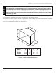
GENERAL INSTALLATION INFORMATION Counter Fireplace � � Figure 1 - Example of a Large Room with 1/2 Wall Divider The following formula can be used to determine the maximum heater rating per the definition of unconfined space: BTU/HR = (L1 + L2) Ft x (W) Ft x (H) Ft x 1000 50 Consider two connecting rooms with an open area between, with the following dimensions: L1 = 151/2 Ft., L2 = 12 Ft., W = 12 Ft., H = 8 Ft.
WARNING FIREPLACE AND HEARTH DIMENSIONS This appliance is for installation only in a solid-fuel burning masonry or UL127 factorybuilt fireplace or in a listed ventless firebox enclosure. It has been design certified for these installations. Exception: DO NOT install this appliance in a factory-built fireplace that includes instructions stating that it has not been tested or should not be used with unvented gas logs. Use manufacturer's installation and clearance requirements as defined in their manual.
PLACEMENT IN A FIREPLACE WITH A RESTRICTIVE BARRIER IMPORTANT INFORMATION FOR THE INSTALLATION OF THIS GAS LOG SET The following are guidelines for placing a gas log set in a fireplace that has a restrictive barrier along the bottom front opening of the fireplace. Some examples of barriers are glass/screen door frames and sunken/recessed fireplaces. Height of Restriction (X) 131/4" No restriction 0 to 1.
WARNING CLEARANCES AND HEIGHT REQUIREMENTS The dimensions shown in Figures 4 through 12 and defined in the fireplace manufacturer's instructions are minimum clearances to maintain when installing this heater. Left and right clearances are determined when facing the front of the heater. When heater is installed into a ventless firebox, minimum clearances, as specified by the ventless firebox manufacturer, must be met. Follow these instructions carefully to ensure safe installation.
CLEARANCES and HEIGHT REQUIREMENTS Heat resistant material (minimum requirements) with no wooden mantel or other combustible projection: To install the gas logs into a fireplace with no wooden mantel, shelf or other combustible projection above the fireplace opening, measure the heat resistant material height, per Figure 5, then See Table A. Heat resistant materials such as slate and marble must be at least 1/2" thick. Sheet metal should not be installed onto combustible material.
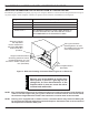
CLEARANCES AND HEIGHT REQUIRMENTS Figure 6 - Measuring Heat Resistant Material for Mantel Heat resistant material (minimum requirements) with wooden mantel or other combustible projection: To install the heater with a wooden mantel, shelf or other combustible projection above, first measure the heat resistant material shown in Figure 6 then see Table B.
CLEARANCES AND HEIGHT REQUIRMENTS ��� �� ����� �� ���� ����� ����� �� ��� ������ ������ ��� Example: The bottom of the mantel may project from the wall a maximum of 21/2" at a minimum of 14" above the opening. The top shelf of the mantel may project a maximum of 6" at a minimum of 201/2" above the opening.
CLEARANCES AND HEIGHT REQUIREMENTS ��� ��� ���� ��� ��� Example: The bottom of the mantel may project from the wall a maximum of 10" at a minimum of 28" above the opening. Figure 9 - Minimum Mantel Clearance with No Hood — DLX24 and DLX28 Figure 10 is an example of an unsafe mantel installation. This mantel projects 4" at 8" above the opening, exceeding the maximum acceptable distance of 21/2" The mantel also projects 7" at 141/2" above the opening, exceeding the maximum acceptable distance of 6".
FLOOR CLEARANCE The gas log heater must be installed at least 5" above any combustible flooring material, such as carpeting or tile, which is closer than 14" to the base of the fireplace. See Figure 11. OR, The gas log heater may be installed nearer to the floor if a minimum of 14" of noncombustible material such as slate or marble is installed between the base of the fireplace and the combustible flooring. See Figure 12.
FIREPLACE PREPARATION BEFORE FULLY INSTALLING THE UNIT: Turn OFF the gas supply to the fireplace or firebox. • WARNING • Seal any fresh air vents and/or ash clean-out doors located on the floor or wall of the fireplace. If left unsealed, drafting may cause pilot outage or sooting. Use a heat resistant sealant. Do not seal the chimney flue damper.
WARNING INSTALLING VENTED APPLICATIONS The fireplace and gas logs function as a system. If the fireplace is spilling into the room (check with a match or a smoke stick), reposition the damper clamp until a positive draft is obtained by opening the damper. If negative pressure in home prevents having a positive draft, contact your dealer for assistance. WARNING PLACING AND SECURING APPLIANCE You must secure the gas log heater to the fireplace floor.
CONNECTING THE GAS CAUTION NOTICE: A qualified gas appliance installer must connect the heater to the gas supply. Consult all local codes. Use new black iron or steel pipe. Internally tinned copper or copper tubing can be used per National Fuel Code, section 2.6.3, providing gas meets hydrogen sulfide limits, and where permitted by local codes. Gas piping system must be sized to provide minimum inlet pressure (Listed on Data Plate) at the maximum flow rate (BTU/Hr).
WARNING CHECKING GAS PRESSURE Connecting directly to an unregulated propane/ LPG tank can cause an explosion. The heater gas inlet connection is a 3/8" NPT at the valve. To connect from the opposite side, route the pipe under the rear portion of the unit. When tightening up the joint to the valve, hold the valve securely to prevent movement. Test all gas joints from the gas meter to the heater valve for leaks using a gas analyzer or soap and water solution after completing connection.
ELECTRICAL WIRING (MILLI-VOLT) The milli-volt valve is a self-powered combination gas control THAT DOES NOT USE 110 VAC TO OPERATE. CAUTION Label all wires prior to disconnection when servicing controls. Wiring errors can cause improper and dangerous operation. Verify proper operation after servicing.
ELECTRICAL WIRING (MILLI-VOLT) CONNECTING REMOTE RECEIVER 1. Plug in the remote connector to the remote receiver wire. 2. Connect the 1/4 female connector to the valve (TPTH and TH terminal). See Figure 19, page 21. 3. Remove the hearthmount coverplate on the remote receiver. (Battery pack must be temporarily removed prior to removing the cover plate). Stick velcro pads with self-adhesive backing to top of remote receiver and to the underside of the unit. See Figure 20. 4.
LOG PLACEMENT WARNING WARNING Before you begin — This unit is supplied with a set of ceramic fiber logs. Do not handle these logs with your bare hands. Always wear gloves to prevent skin irritation from ceramic fibers. After handling logs, wash your hands gently with soap and water to remove any traces of fibers. The positioning of the logs is critical to the safe and clean operation of this heater. Sooting and other problems may result if the logs are not properly and firmly positioned in the appliance.
FLAME APPEARANCE Flames from the pilot, front and rear burner should be visually checked as soon as the heater is installed. In addition, periodically check the flames visually during operation. CHECKING THE PILOT FLAME The pilot flame must always be present when the heater is in operation. It should just touch the top of the thermocouple tip for natural. See Figure 22 and 24 for correct pilot flame. If the pilot flame does not touch the thermocouple, then the main burner cannot function reliably.
CHECKING THE BURNER FLAME In normal operation at full rate after 15 minutes, the following flame appearances should be observed: The rear flames above and behind center log #4, and in front of rear log #1, may be yellow. The flames should extend approximately 2" - 4" above log #4. See Figure 26. Rear Log #1 Center Log #4 Cross Log #5 Log #3 Log #2 Figure 26 - Correct Appearance of Rear Flames The front flames are blue, becoming yellowish as they hit the bumps on the face of log #4.
OPERATING INSTRUCTIONS WARNING FOR YOUR SAFETY READ BEFORE LIGHTING If you do not follow these instruction exactly, a fire or explosion may result causing property damage, personal injury or loss of life. A. This appliance is equipped with an ignition device which automatically lights the pilot. Do not try to light the unit by hand. B. BEFORE OPERATING smell all around the appliance area for gas. Be sure to smell next to the floor because some gas is heavier than air and will settle on the floor.
OPERATING INSTRUCTIONS MANUAL CONTROL LIGHTING INSTRUCTIONS 1. 2. 3. 4. STOP! Read the safety information. Make sure the manual shutoff valve is fully open. This heater is equipped with an ignition device (piezo) which automatically lights the pilot. See Figure 27, page 26 for the location of the piezo ignitor and control knob. Push in gas control knob slightly and turn control knob clockwise to the OFF position. NOTE: Knob cannot be turned to OFF unless knob is pushed in slightly. Do not force. 5.
OPERATING INSTRUCTIONS THERMOSTAT CONTROL LIGHTING INSTRUCTIONS 1. 2. 3. 4. STOP! Read the safety information . Make sure the manual shutoff valve is fully open. This heater is equipped with an ignition device (piezo) which automatically lights the pilot. See Figure 28, page 26 for the location of the piezo ignitor and control knob. Turn control knob clockwise to the OFF position. 5. Wait 5 minutes to clear out any gas. Then smell for gas, including near the floor.
OPERATING INSTRUCTIONS MILLI-VOLT CONTROL LIGHTING INSTRUCTIONS 1. STOP! Read the safety information label. 2. Make sure the manual shutoff valve is fully open. 3. This gas log set is equipped with an ignition device (piezo) which automatically lights the pilot. If piezo ignitor does not light the pilot, See instructions for Match Lighting Instructions, page 30. 4. Turn gas control knob clockwise to the OFF position, set the thermostat to the lowest setting and turn ON/OFF switch to OFF position. 5.
OPERATING INSTRUCTIONS MATCH LIGHTING INSTRUCTIONS 1. Remove any items necessary for easy access to the pilot (for example: logs, screens, etc.). 2. Follow appropriate lighting instructions found previously. Instead of pushing and releasing the piezo button, light a match and hold the flame to the end of the pilot and ignite the pilot. 3. After control knob has been released and pilot stays lit, reinstall any items that were removed for pilot access. 4.
CLEANING AND SERVICING CLEANING AND SERVICING WARNING Annual inspection and cleaning by your dealer or qualified service technician is recommended to prevent malfunction and/or sooting. Turn off heater and allow to cool before cleaning. Disconnect electrical power before cleaning or servicing. Remove fireplace screen. Carefully lower screen from mounting lugs and set aside during cleaning. See instruction manual for installation of screen. DO NOT OPERATE THE UNIT WITH THE SCREEN REMOVED.
WARNING REPLACEMENT PARTS LIST Failure to position the parts in accordance with these diagrams or failure to use only parts specifically approved with this heater may result in property damage or personal injury.
REPLACEMENT PARTS LIST REPLACEMENT PARTS ARE AVAILABLE THROUGH YOUR RETAILER.
WARNING TROUBLESHOOTING Turn appliance OFF and allow to cool before servicing. Only a qualified service person should service and repair the heater. Note: All troubleshooting items are listed in order of operation. REMEDY POSSIBLE CAUSE OBSERVED PROBLEM 1 2. 3. 4. Replace ignitor. Replace ignitor. Reconnect ignitor cable. Free ignitor cable if pinched by any metal or tubing. 5. Replace ignitor cable. 6. Replace piezo ignitor. When ignitor button is pressed, there is no spark at ODS/pilot. 1.
WARNING TROUBLESHOOTING If the gas quality is bad, your pilot may not stay lit, the burners may produce soot and the heater may backfire when lit. If the gas quality or pressure is low, contact your local gas supplier immediately. OBSERVED PROBLEM POSSIBLE CAUSE REMEDY ODS/pilot lights, but flame goes out when control knob is released. 1. Control knob not fully pressed in. 2. Control knob not pressed in long enough. 1. Press in control knob fully. 2.
MONESSEN HEARTH SYSTEMS LIMITED LIFETIME WARRANTY POLICY LIFETIME WARRANTY The following components are warranted for life to the original owner, subject of proof of purchase: Firebox, Combustion Chamber, Heat Exchanger, Grate and Stainless Steel Burners. FIVE YEAR WARRANTY The following components are warranted for 5 years to the original owner, subject of proof of purchase: Ceramic Fiber Logs, Catalytic Filter and Aluminized Burners.