G IN RN WA IRVF2T, IRVF3T, AND IRVF5T MODELS INFRARED UNVENTED ROOM HEATERS WITH THERMOSTAT CONTROL INSTALLATION, OPERATION AND MAINTENANCE MANUAL THE DESIGN OF THIS HEATER COMPLIES WITH STANDARD Z21.11.2 OF THE AMERICAN NATIONAL STANDARDS INSTITUTE AS CERTIFIED BY CSA INTERNATIONAL. THIS APPLIANCE MAY BE INSTALLED IN AN AFTERMARKET, PERMANENTLY LOCATED, MANUFACTURED (MOBILE) HOME, WHERE NOT PROHIBITED BY LOCAL CODES. THIS APPLIANCE IS ONLY FOR USE WITH THE TYPE OF GAS INDICATED ON THE RATING LABEL.
TABLE OF CONTENTS Your heater has been designed for years of safe, efficient, and trouble-free operation provided the instructions in this manual are followed. To help insure your safety, it is very important that you take time to read this entire manual before installing or operating this heater. Important Information ............................................................................................ ..1 Parts Diagram and List ....................................................................
2 IMPORTANT INFORMATION Study these instructions carefully before beginning the installation of this heater. These instructions contain information to be used as a guide during the installation and use of this heater. Critically important safety information is provided in gray blocks along the edges of many pages. These instructions must be followed for safe, efficient, and trouble-free operation of this heater. Before installing the heater, inspect it thoroughly for shipping damage and missing parts.
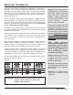
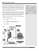
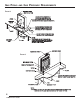
5 PARTS DIAGRAM 16 17 18 19 20 21 22 23 24 8 11 IN WC 555 25 26 27 28 29 TOP RIGHT SIDE FRONT LEFT SIDE 2 53D9012.
6 PARTS LIST All repair part orders should be placed through your local dealer. To ensure prompt and accurate service, please provide the following information when placing a repair part order: Model number of your Appliance, Part Name, Part Number, and Quantity of parts needed. DO NOT TAKE A HEATER NEEDING REPAIR, OR BELIEVED TO BE DEFECTIVE, BACK TO THE SELLER. KEY NO. 1 2 3 4 5 6 7 8 9 10 11 12 13 14 15 16 17 18 19 20 21 22 23 24 25 26 27 28 29 30 DESCRIPTION Cabinet Back Pntd.
HOW THIS APPLIANCE OPERATES Warning: This heater is hot while in operation. Do not touch. Keep children, clothing and furniture away. Never operate this heater without the factory-installed dress guard in place. Never use this heater to dry clothes, cook on, or for any other purpose other than providing heat to the area around the heater. Notice: The heater will go through a curing process during its initial (first 2 to 3 hours) operating period and may emit some smoke and fumes (burning off oil, etc.).
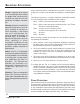
SELECTING A LOCATION These heaters are shipped from the factory equipped for mounting on a flat wall. A wall-mount template is provided with each heater to aid in locating the heater on a wall. Maintaining at least the minimum spacing to combustibles as illustrated by Figure 1 is required for safety. Using the wall-mount template will help ensure that the required minimum clearances between the heater and adjacent walls, floor, and ceiling are maintained when mounting the heater on a wall.
SELECTING A LOCATION Danger: Operation of the heater as a freestanding heater without the proper floor stand correctly installed may lead to fire or the production of carbon monoxide gas. Warning: If heater is installed and operated at clearances less than those specified as minimum in these instructions, a fire hazard may exist with possible fire causing property damage or personal injury.
GAS PIPING AND GAS PRESSURE REQUIREMENTS All gas piping must be installed to comply with local codes or, in the absence of local codes, with the latest edition of the National Fuel Gas Code ANSI Z223.1/NFPA 54. Do not use flexible hose unless the hose is listed by a recognized testing agency for use with gas and is approved by the local code authority. Unions in gas lines shall be of the ground joint type.
GAS PIPING GAS PRESSURE REQUIREMENTS AND FIGURE 2 CONTROL KNOB IGNITOR BUTTON FLOOR STAND REQUIRED IF HEATER IS TO BE INSTALLED AS A FREESTANDING HEATER. (FLOOR STAND SOLD AS AN ACCESSORY.) UNION SHUTOFF VALVE FLOOR PROTECTION REQUIRED FOR ANY COMBUSTIBLE FLOOR MATERIAL OTHER THAN WOOD. FLOOR JOIST 3/8" NPT INLET FITTING FOR GAS SUPPLY IN BOTTOM OF HEATER.
COMBUSTION AND VENTILATION AIR REQUIREMENTS This heater requires fresh air (oxygen) for proper combustion and ventilation. In some cases, but not all, normal air infiltration into a building will supply a sufficient amount of fresh air for proper combustion and ventilation.
COMBUSTION AND VENTILATION AIR REQUIREMENTS Warning: The ODS (Oxygen Depletion Sensor) Pilot safety system is not a substitute for proper installation and use of this appliance. Failure to observe installation and use guidelines in this manual can lead to carbon monoxide poisoning, fire or explosion. Consult your local building inspector or section 5.3 in the latest edition of National Fuel Gas Code ANSI Z223.
INSTALLATION AND ADJUSTMENT Use these instructions as a guide while installing and adjusting the heater. The installation must conform with local codes or, in the absence of local codes, with the latest edition of the National Fuel Gas Code ANSI Z223.1/ NFPA 54. If your heater is to be installed as a wall mounted heater begin with Step 1. If your heater is to be installed as a freestanding heater, begin with Step 10. Use these instructions as a guide while installing and adjusting the heater.
INSTALLATION AND ADJUSTMENT Danger: Excessive torque (twisting) on the inlet fitting of this heater may cause gas leaks at one or more of the fittings inside the heater. 4. Mark locator points on wall; remove template and drive wall-mount anchors through the locator points and into the wall as shown by Figure 5. FIGURE 5 FLAT SURFACES OF ANCHOR BLADES MUST BE PARALLEL TO THE FLOOR. DO NOT INSTALL ANCHOR WITH FLAT SURFACES OF BLADES PERPENDICULAR TO THE FLOOR.
INSTALLATION AND ADJUSTMENT 7. If the heater is to be equipped with an optional blower, install the blower according to the instructions provided with the blower. (Note: IRVF2T heaters cannot be equipped with a blower.) 8. Locate the two key-hole slots on the back of the heater. Align the large openings of the key-hole slots with the mounting screws in the anchors in the wall.
INSTALLATION AND ADJUSTMENT WALL MOUNT AND FREESTANDING INSTALLATION 17. Carefully read the entire "LIGHTING AND OPERATING HEATER" section of this manual, then light the heater’s pilot according to the instructions. The pilot flame should be blue and should appear as indicated by Figure 7. See the "MAINTENANCE" section of this manual for additional information about the pilot.
INSTALLATION AND ADJUSTMENT 20. Immediately after the burner plaques light, use a soapy water solution or a liquid gas leak detector to check all burner tube joints for gas leaks. If any leaks are found, turn the shutoff valve off and repair all leaks before proceeding. Note: During operation, the surface of each burner plaque will glow evenly as shown by Figure 8. Ceramic burner plaques operate with a slightly audible sound when operating correctly.
LIGHTING AND OPERATING HEATER FOR YOUR SAFETY - READ BEFORE LIGHTING WARNING: IF YOU DO NOT FOLLOW THESE INSTRUCTIONS EXACTLY, A FIRE OR EXPLOSION MAY RESULT CAUSING PROPERTY DAMAGE, PERSONAL INJURY OR LOSS OF LIFE. A. This appliance has a pilot which must be lighted by hand. When lighting the pilot, follow these instructions exactly. B. Before lighting smell all around the appliance area for gas. Be sure to smell next to the floor because some gas is heavier than air and will settle on the floor.
LIGHTING AND OPERATING HEATER ALTERNATE METHOD OF LIGHTING THE PILOT WITH A MATCH Follow the steps as if you were going to light the pilot with the push button ignitor i up to the point of pushing down on the control knob to initiate the flow of gas to the pilot. Then: 1. Position yourself where you are not directly in front of the heater and will be able to simultaneously reach the pilot with a burning match and push down on the control knob.
SAFETY CHECKLIST Continued safe operation of this heater requires, but is not limited to, these “Do’s” and “Don’ts”: DO’S: 1. Do make the installation according to local codes or, in the absence of local codes, with latest edition of the National Fuel Gas Code ANSI Z223.1/NFPA 54. 2. Do provide ample fresh air when using heater. 3. Do use only soap-water solution or a liquid gas leak detector when checking for leaks. 4. Do operate the heater only with the factory-installed dress guard in place. 5.
MAINTENANCE To avoid electrical shock, turn off all electrical power to the heater if service is to be performed on a heater that is equipped with an optional blower. It is necessary to KEEP BURNER AND CONTROL COMPARTMENT CLEAN. In even the cleanest homes, lint and dust carried by air moving through the heater will collect on parts of the heater. If allowed to become excessive, this lint and dust will plug the air intakes of the burner and pilot.
TROUBLESHOOTING Due to high temperatures, this appliance must be located out of traffic and away from furniture and draperies. Children and adults should be alerted to the hazard of high surface temperature and should be kept away to avoid burns or clothing ignition. Children should be carefully supervised when in the same room with the appliance. Any safety screen or guard removed for servicing an appliance must be replaced prior to operating the appliance.
WARRANTY LIMITED WARRANTY WHAT IS COVERED AND FOR HOW LONG Monessen Hearth Systems warrants this product to be free from defects in material or workmanship for 5 years from date of purchase, provided the product has been installed, operated, and maintained in accordance with applicable instructions. This warranty covers only the cost of parts and a predetermined labor allowance to restore this heater to proper operating condition. WHAT IS NOT COVERED - Service call to diagnose trouble. - Painted surfaces.
ATTENTION APPLIANCE INSTALLER: PLEASE RETURN THESE OPERATING AND INSTALLATION INSTRUCTIONS TO THE APPLIANCE FOR CONSUMER USE. 53D9012. REV.