VFI Series Vent Free Gas Fireplace Installation and Operating Instructions Models: VFI33L(N/P)(V/I), VFI33C(N/P)(V/I) WARNING: If the information in this manual is not followed exactly, a fire or explosion may result causing property damage, personal injury or loss of life. • • • Do not store or use gasoline or other flammable vapors and liquids in the vicinity of this or any other appliance. WHAT TO DO IF YOU SMELL GAS – Do not try to light any appliance.
VFI33 Vent Free Gas Fireplace System CONTENTS Thank you and congratulations on your purchase of a Vermont Castings Group Fireplace. PLEASE READ THE INSTALLATION AND OPERATION INSTRUCTIONS BEFORE USING THE APPLIANCE. IMPORTANT: Read all instructions and warnings carefully before starting installation. Failure to follow these instructions may result in a possible fire hazard and will void the warranty. Important Safety Information ..................................... 3 Codes ..............................
VFI33 Vent Free Gas Fireplace System IMPORTANT SAFETY INFORMATION INSTALLER OWNER Please leave these instructions with the appliance. Please retain these instructions for future reference. WARNING: • Any change to this heater or its controls can be dangerous. • Improper installation or use of the heater can cause serious injury or death from fire, burns, explosion or carbon monoxide poisoning. • Do not allow fans to blow directly into the fireplace. Avoid any drafts that alter burner flame patterns.
VFI33 Vent Free Gas Fireplace System 21. 22. 23. 24. 25. IMPORTANT SAFETY INFORMATION The initial break-in operation should last four hours with the burner at the highest setting. Provide maximum ventilation by opening windows or doors to allow odors to dissipate. Any odors remaining after this initial break-in period will be slight and will disappear with continued use. Input ratings are shown in BTU per hour and are for elevations up to 2,000 feet.
VFI33 Vent Free Gas Fireplace System PRODUCT FEATURES GAS SPECIFICATIONS & ORIFICE SIZE VFI33 CONTROLS MODEL Surround FUEL CONTROL MAX. INPUT MIN. INPUT ORIFICE (BTU/h) (BTU/h) SIZE 28,000 19,000 #38 VFI33LNV NAT. Millivolt VFI33LPV LP. Millivolt 27,000 22,000 #52 VFI33CNV NAT. Millivolt 28,000 19,000 #38 VFI33CPV LP. Millivolt 27,000 22,000 #52 VFI33LNI NAT. IPI 28,000 19,000 #38 VFI33LPI LP. IPI 27,000 22,000 #52 VFI33CNI NAT.
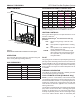
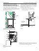
VFI33 Vent Free Gas Fireplace System FRAMING DIMENSIONS Cold Climate Switch Master Switch Figure 2 Cold Climate Option mode (as it comes from the factory), your pilot remains unlit until needed, saving you fuel. Standing pilot mode, by comparison, is characterized by a continuously burning pilot. The benefit of a pilot which lights only when needed is fuel savings. However, with no pilot burning in your fireplace, units operating in colder climates may experience delayed start up or lock out.
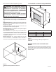
VFI33 Vent Free Gas Fireplace System PRE-INSTALLATION INFORMATION FRAMING DIMENSIONS If unit is to be “built in,” fireplace framing can be built before or after the appliance is set in place. BE SURE THAT ALL PACKING MATERIAL HAS BEEN REMOVED FROM THE UNDERSIDE OF THE UNIT PRIOR TO SETTING THE FIREBOX IN PLACE. Construct fireplace framing following Figure 2. Refer to Figure 5 on Page 9 for fireplace dimensions. The framing headers may not rest directly on top of the firebox.
VFI33 Vent Free Gas Fireplace System CLEARANCE and HEIGHT REQUIREMENTS WARNING: The dimensions shown in Figures 4 and 5 and defined in the fireplace manufacturer's instructions are minimum clearances to maintain when installing this heater. Left and right clearances are determined when facing the front of the heater. 22 3 /4 A Follow these instructions carefully to ensure safe installation. Failure to follow instructions exactly can create a fire hazard.
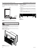
VFI33 Vent Free Gas Fireplace System CLEARANCES HEAT RESISTANT MATERIAL (MINIMUM REQUIREMENTS) WITH NO WOODEN MANTEL OR OTHER COMBUSTIBLE PROJECTION Heat resistant material (minimum requirements) with wooden mantel or other combustible projection: To install the heater with a wooden mantel shelf or other combustible projection above, first measure the heat resistant material shown in Figure 6. Figure 8 is an example of an unsafe mantel installation.
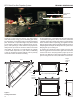
VFI33 Vent Free Gas Fireplace System The gas log heater must be installed at least 5" above any combustible flooring material, such as carpeting or tile, which is closer than 14" to the base of the fireplace. Figure 8 5" Noncombustible Material CLEARANCES and INSTALLATION INSTALL CANOPY 1. Remove the fireplace screen as described in the previous section. 2. Align canopy with the holes in the top frame assembly. Figure 10 3.
INSTALLATION VFI33 Vent Free Gas Fireplace System SECURE HEATER TO FLOOR 2. Lift grate and base assembly out of the firebox. NOTE: Clearance requirements as detailed in “Clearances and Height Requirements” section of this manual must be met before securing heater in place. 3. Secure the firebox with two anchoring screws (3⁄16" x 11⁄2" length) supplied with the fireplace system. Figure 14 To prevent movement, the heater must be secured to the floor or hearth. 1.
VFI33 Vent Free Gas Fireplace System CONNECT GAS LINE CONNECTING THE GAS LINE NOTICE: A qualified gas appliance installer must connect the heater to the gas supply. Consult all local codes. WARNING: Use new black iron or steel pipe. Internally tinned copper or copper tubing can be used per National Fuel Code, section 2.6.3, providing gas meets hydrogen sulfide limits, and where permitted by local codes.
VFI33 Vent Free Gas Fireplace System GAS PRESSURE — MILLIVOLT CHECKING GAS PRESSURE: MILLIVOLT CONTROL Figure 17 The valve regulator controls the burner pressure which should be checked at the pressure test point. Turn captured screw counter clockwise two or three turns and then place tubing to pressure gauge over test point (Use test point “OUT” closest to control knob). After taking pressure reading, be sure and turn captured screw clockwise firmly to re-seal. Do not over torque. Check for gas leaks.
VFI33 Vent Free Gas Fireplace System ELECTRICAL WIRING — MILLIVOLT ODS Pilot On/Off Switch ODS Pilot Field Installed Optional Wall Switch or Remote Receiver Valve On/Off Switch Spade Terminal TH = 3 TP = 1 TP/TH = 2 Switch Figure 18 Wiring Diagram WARNING: Label all wires prior to disconnection when servicing controls. Wiring errors can cause improper and dangerous operation. Verify proper operation after servicing.
VFI33 Vent Free Gas Fireplace System ELECTRICAL WIRING — MILLIVOLT CONNECT REMOTE RECEIVER THESE INSTRUCTIONS SUPERCEDE THE SECTION ENTITLED “HEARTH MOUNT” IN THE MILLIVOLT HAND-HELD REMOTE INSTRUCTIONS SUPPLIED WITH THE REMOTE. Figure 19 1. Remove bottom control door. 2. Connect the remote connector wires located in the unit to the remote receiver. 3. Stick Velcro® pads with self-adhesive backing to bottom of remote receiver and to floor of compartment behind access panel. 4.
VFI33 Vent Free Gas Fireplace System OPERATING INSTRUCTIONS – MILLIVOLT FOR YOUR SAFETY READ BEFORE LIGHTING WARNING: If you do not follow these instruction exactly, a fire or explosion may result causing property damage, personal injury or loss of life. A. This appliance is equipped with a pilot which must be lit with built-in piezo ignitor while following these instructions exactly. B. BEFORE OPERATING smell all around the appliance area for gas.
VFI33 Vent Free Gas Fireplace System OPERATING INSTRUCTIONS — MILLIVOLT LIGHTING PILOT FOR THE FIRST TIME APPROVED LEAK TESTING METHOD You may check for gas leaks with the following methods only: • Soap and water solution • An approved leak testing spray • Electronic sniffer NOTE: Remove any excessive pipe compound from the connections. Excessive pipe compound can set off electronic sniffers. WARNING: If using a soap and water solution to test for leaks, DO NOT spray solution onto control body.
VFI33 Vent Free Gas Fireplace System OPERATING INSTRUCTIONS – MILLIVOLT LIGHTING BURNER LIGHTING THE BURNER Depress and turn the knob counterclockwise to the “ON” position. It will take less than four (4) seconds for the burner to ignite. MAIN BURNER SWITCH This switch allows you to turn on and to turn off the main burner without using the gas valve knob. is in the “ON” position to light the main burner.
GAS PRESSURE & ELECTRICAL INSTALLATION — IPI VFI33 Vent Free Gas Fireplace System CHECK GAS PRESSURE – IPI 1. Check gas type. The gas supply must be the same as stated on the appliance’s rating decal. If the gas supply is different from the fireplace, STOP! Do not install the appliance. Contact your dealer immediately. 2. To facilitate easier installation, a 18" (610 mm) flex line with manual shut-off valve has been provided with this appliance. Install and attach 1/2" gas line onto shut-off valve. 3.
VFI33 Vent Free Gas Fireplace System WALL SWITCH INSTALLATION The wall switch wire connection is located off the wire harness coming out of the IPI Control Board. The label is wired 'wall switch'. Connect the low voltage switch wires to the two (2) terminals labeled "wall switch" from the control ELECTRICAL INSTALLATION – IPI board. Run wire to desired location on wall. Up to 50 feet of 18 gauge wire may be used if necessary. Attach wires to wall switch.
OPERATING INSTRUCTIONS – IPI VFI33 Vent Free Gas Fireplace System FOR YOUR SAFETY READ BEFORE LIGHTING WARNING: If you do not follow these instructions exactly, a fire or explosion may result causing property damage, personal injury or loss of lie. A. This appliance is equipped with an ignition device which automatically lights the pilot. Refer to the instructions. B. BEFORE OPERATING smell all around the appliance area for gas.
VFI33 Vent Free Gas Fireplace System OPERATING INSTRUCTIONS – IPI OPERATIONS AND INDICATIONS Cold Climate Switch RF Learn Button Master Switch System Set Up Chart NOTE: When using ON/OFF wall switch, the master switch, located in bottom of fireplace must be in the ON position to perform all configuration setup operations. FUNCTION OPERATION DEFAULT SETTING Cold Climate Pilot On/Off Flip the toggle switch to ON.
VFI33 Vent Free Gas Fireplace System ELECTRICAL WIRING – FAN WARNING: This fireplace has a threeprong, grounded electrical plug. This plug helps protect you against electrical shock. Only connect plug to a properly grounded, three-prong receptacle. Do not cut or remove the grounded prong from this plug. IMPORTANT: Always check local building codes. The installation must comply with local regulations as well as the national electric codes.
VFI33 Vent Free Gas Fireplace System LOG PLACEMENT CAST IRON GRATE INSTALLATION WARNING: The positioning of the logs is critical to the safe and clean operation of this heater. Sooting and other problems may result if the logs are not properly and firmly positioned in the appliance. Never add additional logs or embellishments such as pine cones, vermiculite or rock wool to the heater. Only use the logs and 2G-RW rock wool (for NB18) supplied with the unit.
VFI33 Vent Free Gas Fireplace System LOG PLACEMENT ROCK WOOL PLACEMENT Before installing logs, place rock wool in dime size pieces evenly over small burner ports starting in the rear of the burner going towards the front. Avoid placing rock wool on slots on each side of rear burner and on large yellow flame ports on front of burner. After covering small burner ports, discard any excess rock wool. Figure 25 2. Place front right log (#2) on right pin located on burner and right grate bar. Figure 27.
VFI33 Vent Free Gas Fireplace System LOG PLACEMENT 5. Place left front log (#5) on left pin located on burner and left grate bar. Rest top right portion of log on right front log. Figure 30 Left Top Log #7 Right Top Log #8 Left Front Log #5 Figure 32 Place Right Top Log #8 6. Place top left log (#6) on unit by placing grooved portion of log onto left grate bar with bark facing outward. Rest front part of log in groove on left front log.
VFI33 Vent Free Gas Fireplace System LOG PLACEMENT INSTALL 18", (F,R) HIGHLAND OAK LOGS ON NATURAL BLAZE BURNER (AVAILABLE FOR MAJESTIC SYSTEMS ONLY) Right Rear Log #3 1. Place the #1 log (the “chunk”) on the grate bar right side of the burner adjacent to the controls. Figure 33 Ember Chunk Log #1 Figure 35 4. Place left rear log (#4) on pin located on rear support bracket on left side and left grate bar. Figure 36 Figure 33 Left Rear Log #4 2.
VFI33 Vent Free Gas Fireplace System 6. Place top left log (#6) on left rear log (#4) and left front log (#5) using locating grooves on bottom of #6 and locating blocks on logs #4 and #5. Figure 38 7. Place right top log (#7) on right rear log (#3) and right front log (#2) using locators on the bottom of log #7 and locators on logs #2 and #3. Figure 38 Right Top Log #7 PLACE THE DECORATIVE ROCK Optional volcanic rock may be placed around the unit on the floor of the firebox.
VFI33 Vent Free Gas Fireplace System LOG PLACEMENT KENTUCKY WILDWOOD KW18-R, KW24-R AND KW30-R LOGS PLACEMENT 4. Place bottom front left log #4 on left pin located on burner and left grate bar. (AVAILABLE FOR MONESSEN AND MAJESTIC SYSTEMS) 1. Place bottom front right log #1 on right pin located on burner and right grate bar. Log #1 Log #4 Figure 43 Figure 40 2. Place bottom rear right log #2 on pin on rear of grate assembly and push towards rear as far as possible. 5.
VFI33 Vent Free Gas Fireplace System FLAME APPEARANCE & OPERATING INSTRUCTIONS 7. Place top right log #7 on the two (2) pins located on log #2 and log #1. Log #7 Thermocouple for Natural Thermocouple for LP Figure 48 Incorrect Appearance of Pilot Flame Figure 46 THERMOSTAT AND MILLIVOLT CONTROL VISUAL FLAME CHECK Flames from the pilot, front and rear burner should be visually checked as soon as the heater is installed. In addition, periodically check the flames visually during operation.
VFI33 Vent Free Gas Fireplace System OPERATING INSTRUCTIONS FOR YOUR SAFETY READ BEFORE LIGHTING WARNING: If you do not follow these instruction exactly, a fire or explosion may result causing property damage, personal injury or loss of life. A. This appliance is equipped with a piezo ignition device which automatically lights the pilot. If the piezo is not working properly see Match Lighting Instructions on Page 24. B. BEFORE OPERATING smell all around the appliance area for gas.
VFI33 Vent Free Gas Fireplace System OPERATING INSTRUCTIONS MILLIVOLT/THERMOSTAT CONTROL LIGHTING INSTRUCTIONS 1. STOP! Read the safety information label. 2. Make sure the manual shutoff valve is fully open. 3. This gas log set is equipped with an ignition device (piezo) which automatically lights the pilot. If piezo ignitor does not light the pilot, refer to instructions for “Match Lighting Instructions,” page 33. 4.
VFI33 Vent Free Gas Fireplace System OPERATING INSTRUCTIONS MATCH LIGHTING INSTRUCTIONS 1. Remove any items necessary for easy access to the pilot (for example: logs, screens, etc.). 2. Follow appropriate lighting instructions found previously. Instead of pushing and releasing the piezo button, light a match and hold the flame to the end of the pilot and ignite the pilot. 3. After control knob has been released and pilot stays lit, reinstall any items that were removed for pilot access. 4.
VFI33 Vent Free Gas Fireplace System CLEANING AND SERVICING WARNING: Turn off heater and allow to cool before cleaning. Disconnect electrical power before cleaning or servicing. ANNUAL CLEANING/INSPECTION— PERIODIC CLEANING— Refer to parts diagram for location of items discussed below. Refer to parts diagram for location of items discussed below. Annual inspection and cleaning by your dealer or qualified service technician is recommended to prevent malfunction and/or sooting.
VFI33 Vent Free Gas Fireplace System WARNING TROUBLESHOOTING WARNING: Turn appliance OFF and allow to cool before servicing. Only a qualified service person should service and repair the heater. NOTE: All troubleshooting items are listed in order of operation. OBSERVED PROBLEM POSSIBLE CAUSE When ignitor button is pressed, 1. Ignitor electrode positioned wrong. there is no spark at ODS/pilot. 2. Ignitor electrode is broken. 3. Ignitor electrode not connected to ignitor cable. 4.
VFI33 Vent Free Gas Fireplace System OBSERVED PROBLEM POSSIBLE CAUSE ODS/pilot lights, but flame 1. Control knob not fully pressed in. goes out when control knob is 2. Control knob not pressed in long released. enough. 3. Manual shutoff valve not fully open. 4. Thermocouple connection loose at control valve. 5. Pilot flame not touching thermocouple, which allows thermocouple to cool, causing pilot flame to go out.
VFI33 Vent Free Gas Fireplace System REPLACEMENT PARTS FIREBOX ASSEMBLY 7 7 4 7 5 7 6 7 7 2 7 10 1 3 9 8 REFERENCE NO. DESCRIPTION QTY. REPLACEMENT PART NO. 1. Screen Assembly 1 20306285 2. Canopy Assembly 1 20307546 3. Lower Control Panel 1 20306484 4. Left Firebrick 1 20307263 5. Center Firebrick 1 20307264 6. Right Firebrick 1 20307262 SURROUND 7. 33" x 43" Small Black Surround 1 VFICFSS 7.
VFI33 Vent Free Gas Fireplace System REPLACEMENT PARTS MILLIVOLT BURNER ASSEMBLY 1 4 3 2 CONTEMPORARY BURNER TRADITIONAL BURNER 5 9 10 7 6 8 11 REF DESCRIPTION QTY VFI33CNV VFI33CPV VFI33LNV VFI33LPV 1 On/Off Switch 1 32D0232 32D0232 32D0232 32D0232 2 Piezo Ignitor 1 14D0503 14D0503 14D0503 14D0503 3 ODS Pilot Assembly 1 14D0473 14D0477 14D0473 14D0477 4 Piezo Wire 1 00K0632 00K0632 00K0632 00K0632 5 Control Valve 1 14D0467 14D0468 14D0467 14D0468 6 P
VFI33 Vent Free Gas Fireplace System REPLACEMENT PARTS IPI BURNER ASSEMBLY 2 1 5 4 3 6 CONTEMPORARY BURNER TRADITIONAL BURNER 10 12 7 8 9 11 REF DESCRIPTION QTY VFI33CNI VFI33CPI VFI33LNI VFI33LPI 95E0111 95E0111 95E0111 1 Cold Climate Switch 1 95E0111 2 On/Off Switch 1 32D0232 32D0232 32D0232 32D0232 3 Gas Valve 1 95E0101 95E0102 95E0101 95E0102 4 Control Box 1 95E0100 95E0100 95E0100 95E0100 5 ODS Module 1 20303179 20303179 20303179 20303179 6 ODS Pil
VFI33 Vent Free Gas Fireplace System REPLACEMENT PARTS FOR MONESSEN BRANDED SYSTEMS: 7 6 4 3 5 2 8 1 (BENEATH #8) BERKLEY OAK REFRACTORY LOGS REF. DESCRIPTION QUANTITY BO18-R BO18-F 1. Ember Chunk 1 81D0110 81D0109 2. Right Front Log 1 81D0059 81D0083 3. Right Rear Log 1 81D0060 81D0084 4. Left Rear Log 1 81D0061 81D0085 5. Left Front Log 1 81D0062 81D0086 6. Middle Left Log 1 81D0063 81D0087 7. Left Top Log 1 81D0064 81D0088 8.
VFI33 Vent Free Gas Fireplace System REPLACEMENT PARTS FOR MAJESTIC BRANDED SYSTEMS: 6 4 7 3 8 5 1 2 (BENEATH #7) HIGHLAND OAK REFRACTORY LOGS REF. DESCRIPTION QUANTITY HO18-R HO18-F 1. Ember Chunk 1 81D0110 81D0109 2. Right Front Log 1 81D0011 81D0035 3. Right Rear Log 1 81D0012 81D0036 4. Left Rear Log 1 81D0013 81D0037 5. Left Front Log 1 81D0014 81D0038 6. Left Top Log 1 81D0015 81D0039 7. Right Top Log 1 81D0016 81D0040 8.
VFI33 Vent Free Gas Fireplace System REPLACEMENT PARTS FOR MONESSEN OR MAJESTIC BRANDED SYSTEMS: 7 3 6 2 5 1 4 KENTUCKY WILDWOOD REFRACTORY LOGS REF DESCRIPTION QUANTITY KW18-R 1. Bottom front right log, #1 1 20305902 2. Bottom rear right log, #2 1 20305903 3. Bottom rear left log, #3 1 20305904 4. Bottom front left log, #4 1 20305905 5. Center left log, #5 1 20305906 6. Center top log, #6 1 20305907 7.
VFI33 Vent Free Gas Fireplace System LIMITED LIFETIME WARRANTY POLICY LIFETIME WARRANTY The following components are warranted for life to the original owner, subject to proof of purchase: Firebox, Combustion Chamber, Heat Exchanger, Grate and Stainless Steel Burners. FIVE YEAR WARRANTY The following components are warranted for 5 years to the original owner, subject of proof of purchase: Ceramic Fiber Logs, Catalytic Filter and Aluminized Burners.
149 Cleveland Drive • Paris, Kentucky 40361 www.vermontcastingsgroup.