MONITOR REFERENCE o w n e r s m a n u a l m o n i t o r a u d i o . c o . u k Monitor Ref Manual Rev1.2.
Monitor Ref Manual Rev1.2.
Contents Page Introduction 1 Positioning 2 AV Positioning 2 2 Channel Positioning 3 Spike Fixing 3 Wiring Configurations 4 Port Bungs 5 Amp Panel & Controls 6 Positioning & Initial set Up of MRW-10 8 Set Up 9 Trouble Shooting 9 Specifications 10 Owner Information 11 introduction Thank you for purchasing the Monitor Reference Series loudspeakers.
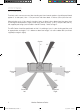
positioning AV Positioning The front, and in some cases rear, floor standing and stand mount speakers should be positioned approx 6 - 9 feet apart (1.8m - 2.5m) and start with them about 10 inches (25cm) from the wall. When playing music, if the sound is too bass heavy or there is bass boom from the room, then try moving the loudspeakers slightly further away from the wall(s). If this is not possible, then try the supplied port bungs (not included in the MR Centre). Refer to Page 5.
2 Channel Positioning For use in a 2 channel system, the listening position and the loudspeakers should form an equilateral triangle. The speakers should be positioned approximately 6 - 10 feet (1.8 - 3m) apart. They ideally need to be between 8 - 18 inches (20 - 45cm) away from the rear and 3 feet (1m) from the side walls. Experimentation is strongly advised when initially setting up your speakers, as environments and personal preference differ with each installation.
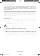
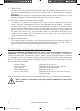
Wiring configurations Single Wire For the MR1 and MR Centre, there are only one pair of terminals (as in illustration opposite). This means it is only possible to single wire these speakers. Single Wire The MR2, MR4 & MR6 all have two pairs of terminals. By running one pair of cables (one positive and one negative) you will be single wiring them. When single wiring these speakers, you must leave the terminal links in.
Port bungs WARNING: Care must be taken not to insert the port bungs too far into the port, as this may result in the foam bung being lost inside the cabinet. If the loudspeaker is to be installed in a small room, typically 9 sqM ( 80 sqFT), or a room known to reproduce accentuated bass response, it may be desirable to fit port bungs. However, experimentation is recommended with positioning of the loudspeaker in the room prior to fitting.
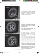
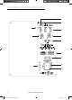
Amp Panel & Controls for MRW-10 Title : MONITOR MRW-10 AMP PANEL ARTWORK Date: 2ND MARCH 2011 PAINTED TEXT : WHITE FONT : HELVETICA & ARIAL 1 2 5 3 6 4 7 TO RE COV RE AFIN DE RÉD LE COUVERCLE PAR L’UTILIS 8 9 10 11 10a Notes: 1. ARTWORK SCREENPRINTED ON. 2. COLOUR : WHITE 6 Monitor Ref Manual Rev1.2.
1. Power Mode Switch with On-Auto-Off Facility The Power Mode Switch has three positions: ‘On’–‘Auto’–‘Off’. With the switch in the ‘On’ position, the subwoofer is permanently switched on under all conditions. In the ‘Auto’ position the subwoofer will automatically switch on when an input signal is received and will remain on until no signal is received for around 10-15 minutes, the MRW-10 will then switch into standby mode until a signal is received once more.
9. Power Switch The Mains Power Switch should be switched to the ‘Off’ position when the MRW-10 will not be used for extended periods. The switch must be in the ‘On’ position for the subwoofer to function. WARNING: Due to the mains switch being located on the rear panel, the apparatus must be located in the open area with no obstructions to access the mains switch. 10. IEC Mains Power Connector/ Fuse Location The MRW-10 is supplied with a two-pin mains input socket for connection to the mains supply.
Set Up Once the input cables are connected and the controls are set in accordance with the initial set-up procedure above, the subwoofer can be connected to the mains power supply and switched on at the mains power switch. • For use with an AV amp/ receiver (product with sub woofer output) run the auto set up on the AV amp. Check the settings it has supplied and carry out fine adjustment if necessary. This may include adjusting the gain or crossover frequency on the AV amp or level on the sub woofer.
MRW-10 Drive unit Complement Bass Alignment Recommended Amp Requirements Power Handling (RMS) Nominal Impedance Sensitivity (1w @ 1m) Frequency Response Model 260 x 165 x 180 1 x 5.5” MMP®II Bass/ Mid driver. 1 x 1” (25mm) C-CAM® gold dome tweeter Bass Reflex – Rear Ported. 15 - 70W 70W 6 Ohms 88dB 55Hz - 30kHz MR1 350 x 185 x 250 1 x 6.5” MMP®II Bass/ Mid driver. 1 x 1” (25mm) C-CAM® gold dome tweeter Bass Reflex – Front Ported.
Owner Information Product Details Model ................................................................. Product Serial No ................................................ Date of Purchase ................................................ Dealer Details Dealer Name ..................................................................................................................... Address ........................................................................................................................
Monitor Ref Manual Rev1.2.
Monitor Ref Manual Rev1.2.
m o n i t o r a u d i o . c o . u k Monitor Audio Ltd. 24 Brook Road Rayleigh, Essex SS6 7XJ England Tel: +44 (0)1268 740580 Fax: +44 (0)1268 740589 Email: info@monitoraudio.co.uk Web: www.monitoraudio.com Designed in the United Kingdom © 2011. Version 1 Monitor Ref Manual Rev1.2.