Enter Serial No. here MANUAL No.Y-BX-25UL In the event of an enquiry please quote this serial number.
APPROVED TO ANSI/UL 197 9th EDITION 2003 WARNING LABEL, TO REDUCE RISK OF FIRE OR ELECTRIC SHOCK DO NOT REMOVE COVER (OR BACK) NO USER SERVICEABLE PARTS INSIDE REPAIR SHOULD BE DONE BY AUTHORIZED PERSONNEL ONLY Failure to follow the cleaning and maintenance instructions detailed in this owners manual could affect the warranty of this oven.
CONTENTS PAGE 4 PART 1.0 Introduction. 5 PART 2.0 Dimensions. 6 PART 3.0 Specifications. 7 PART 4.0 Safety. 8 PART 5.0 Installation. 10 PART 6.0 Isolation. 7 PART 7.0 Daily Cleaning. 8 PART 8.0 Weekly Cleaning. 14 PART 9.0 SMARTBAKE operating instructions 19 PART 10.0 SMARTBAKE programming instructions. 22 PART 11.0 Using ”MONOLINK 6” programming software. 27 PART 12.0 Light bulb Replacement. 28 PART 13.0 Replacement parts list. 30 PART 14.0 Electrical information.
1.0 INTRODUCTION The BX-DD Smartbake oven is a computerised, compact, electric convection oven with steam capability and a capacity of three 26” x 18” trays. The oven is constructed of stainless steel and features the state of the art smartbake controller with color display and 99 programmable recipes each with up to six steps in which the bake time, temperature, steam time, fan and vent can be controlled. Designed to be stackable, without the requirement for a separate support.
2.0 DIMENSIONS EACH OVEN: Height: Depth, door closed: Width: 20.75" 46" 34" 2" (50mm) clearance is required at the back and sides of the oven to allow adequate circulation of air.
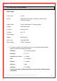
3.0 SPECIFICATIONS EACH OVEN: Total Power: 7.5 kW. Electric: 208V/220V Three phase + Neutral + Ground; 60Hz. 24Amps per phase. Supply Cable: 6 feet of cable with L21-30 plug supplied. Loading: 7kW Ring element Fan Drive: Direct to motor Tray Size: 26” x 18” Tray Capacity: 3. Damper: Butterfly type. Noise Level: Less than 85dB. Water Supply: 20 PSI Cold water.
4.0 SAFETY To safely use this convection oven, read this owners manual completely and follow these warnings and the other warnings in this manual while operating the oven. • The oven is designed for the baking of bread, confectionery and savoury products. Do not use it for baking other items without first consulting Adamatic. • All repairs and maintenance of electrical units must only be carried out by an authorized Adamatic service technician.
5.0 INSTALLATION Water Supply; It is the customer’s responsibility to provide an appropriate water treatment system that will supply water that meets the water specification listed on page 6. The supply must be provided with a shut-off valve, pressure reduction valve and pressure gauge. NOTE A RUBBER WASHER SHOULD BE FITTED TO ENSURE A FULL SEAL WITH WATER SUPPLY. (Part Number A900-05-261) • Ambient temperatures : Maintain ambient temperatures below 115° F (40° C) around the oven.
• Stacking two ovens 1. Position ovens one on top of the other. 2. Remove both ovens rear covers. Or Remove front control panels (complete with electrics and cables) and work from the front of the ovens. 3. Remove blanking plate (fixed with silicone sealant) from damper tube of upper oven. 4. Fit end of flexible ducting over top damper tube and attach to lower oven damper tube. Use silicone sealant and worm drive clips to fasten in position. 5.
6.0 ISOLATION To stop the oven in an emergency, Unplug the oven from the outlet.
7.0 DAILY CLEANING INSTRUCTIONS NOTE: UNPLUG THE OVEN FROM OUTLET AND ALLOW TO COOL COMPLETELY BEFORE CLEANING • The equipment is to be cleaned daily using approved chloride – free cleaners. • NEVER USE STEEL WOOL TO CLEAN OVEN. • Sweep any debris (after it has been allowed to cool) from oven interior surfaces onto oven removable catch tray and remove for cleaning.
8.0 WEEKLY CLEANING INSTRUCTIONS NOTE: • BEFORE CLEANING UNPLUG THE OVEN FROM OUTLET AND ALLOW TO COOL COMPLETELY Complete daily check then: The inner door glass is hinged to enable cleaning of internal surfaces. To open, remove the two screws shown below. The internal surfaces of the door glass can then be cleaned using a suitable glass cleaner.
IMPORTANT: 1) WHEN CLEANING INSIDE OVEN, CARE MUST BE TAKEN NOT TO DAMAGE TEMPERATURE PROBE PROTRUDING FROM UPPER CORNER OF CHAMBER REAR WALL. (SEE BELOW) 2) TO AVOID ELECTROCUTION OR OVEN DAMAGE –NEVER ALLOW WATER, STEAM, CLEANING SOLUTION, OR OTHER LIQUIDS TO ENTER THE ELECTRICAL PANELS OR CONNECTIONS. 3) DO NOT REMOVE THE REAR PANEL INSIDE THE OVEN.THIS ALLOWS ACCESS TO THE FAN ASSEMBLY AND COULD CAUSE INJURY.
9.
1. Connect water ensuring there are no leaks. 2. Plug oven into appropriate wall outlet. 3. Turn oven on by pressing green main power button, and the following screen (fig 1) will appear: - Fig 1 4. Press control button (4) under select product icon and program list appears (see fig 2). Fig 2 5. Highlight the desired program by pressing control button (2) under the scroll down icon or control button (3) under the scroll up icon. NOTE.
7. Choose 1, 2 or 3 pan capacity by pressing the appropriate control button under the icon and oven will start to preheat. (Fig3) Fig 3 To stop heating press stop button at any time.
8. When oven is ready it will beep three times and the following screen will appear (fig 4). Load product and press control button (4) under the start icon Fig 4 9. If a turn pan time has been programmed, a buzzer will sound when the timer reaches 0. Open the door, remove tray and turn around then replace it back in the oven. Close the door to silence the buzzer and continue the bake cycle. 10. At the end of bake time, buzzer will sound, and (fig 5) will be displayed. Open door and check product.
11. This will now take you back to program list screen (Fig 2, Page 15). 12. To bake in pre-heated oven, repeat from step 5. NOTE: During heating (1) can be pressed at any time to check settings. (Press (1) or wait 10 seconds to return to previous screen). 1 Until oven is up to temperature the display will show “ HEATING”. When correct temperature is reached display will show “READY”. The oven will keep to set temperature until bake is started.
10.
1. Press stop to get to first screen Fig 6 Fig 6 2. Press and hold button 2 for 5 seconds for pass code screen Fig 7. Fig 7 3. Enter pass code (default 111111). Fig 8 will appear. Fig 8 4. Use scroll buttons to highlight the required product. Press enter. All parameters can now be set.
The oven is capable of six different phases per bake and if a lower number is required, bake time can be left at “0” to leave that phase inoperative.
PROGRAMMING INSTRUCTIONS (UPLOAD/DOWNLOAD) USING “MONOLINK 6” SOFTWARE 11.0 SETTING UP THE CONNECTION 1. Ensure that “MONOLINK 6” is installed on your computer and the oven is showing the start screen (Dunkin Donut logo) 2. Connect oven to the computer using a null modem cable A as shown below. (2 X 9 WAY D-TYPE CONNECTOR – BOTH FEMALE) A NULL MODEM CABLE (2 X 9 WAY D-TYPE CONNECTOR – BOTH B USB – SERIAL ADAPTOR WILL BE NEEDED IF A SERIAL PORT IS NOT AVAILABLE ON THE COMPUTER BEING USED.
SETTING UP THE PROGRAM 1. Start “MONOLINK 6” on the computer. 2. Go to “configure / units” and ensure that “Degrees Fahrenheit” is ticked. 3. Go to “configure / oven” and ensure that “Rainbow Dunkin Donuts” is ticked.
TO CHANGE A PROGRAM 1. Go to “file / open” 2.
3. Highlight the product to change 4. Remember to choose 1 pan, 2 pan, or 3 pan, then click on the information to be changed. Enter the new number and press return. 5. Go to “file/save” to save the changes or “file /save as” to save as a different file.
TO DOWNLOAD PROGRAM TO OVEN 1. Ensure the computer is connected to the oven and the correct program is loaded on the screen, then go to “Communications/Download recipes (to oven)” The oven will show a counter (up to 99) in the corner of the screen which will disappear when the download is complete.
12.0 LIGHT BULB REPLACEMENT 14.0 B REPLACEMENT Replacement bulb part number B772-94-001 In the event of a bulb failure, Instructions on how to change a bulb are as follows: • Unplug oven from wall outlet and allow oven to cool completely. • Remove screws (4 per light) and take glass, frame and gasket off lamp unit. SCREWS • Remove bulb by unscrewing in direction of arrow and replace with new bulb. GASKET Pt No.B721-67-008 GLASS AND FRAME Pt No.B721-67-010 Pt No.
13.
FG 189 3-218 26 x18 UL 3 TRAY (COLOUR) Dunkindonut full JKleva edit5 known as smartbake in USA 5-08 RAC 29 DOOR SEAL OUTER DOOR GLASS INNER DOOR GLASS HANDEL BLUE WATER HOSE WATER INLET ASSY DRIP TRAY TRAY RUNNER RH TRAY RUNNER LH MECHANICAL PARTS M159-03-01500 M159-03-11000 M159-03-20800 A900-27-118 A900-34-087 M158-17-00300 M205-12-00500 M189-01-01400 M189-01-01401
14.
208V – 220V 60Hz , 3PH + NEUTRAL + GROUND and 120v 1PHASE + N + GROUND FG 189 3-218 26 x18 UL 3 TRAY (COLOUR) Dunkindonut full JKleva edit5 known as smartbake in USA 5-08 RAC 31
CONTROL PANEL WIRING DIAGRAM FG 189 3-218 26 x18 UL 3 TRAY (COLOUR) Dunkindonut full JKleva edit5 known as smartbake in USA 5-08 RAC 32
CONTROL PANEL OUTPUT SCHEMATIC FG 189 3-218 26 x18 UL 3 TRAY (COLOUR) Dunkindonut full JKleva edit5 known as smartbake in USA 5-08 RAC 33
110V WIRING SCHEMATIC FG 189 3-218 26 x18 UL 3 TRAY (COLOUR) Dunkindonut full JKleva edit5 known as smartbake in USA 5-08 RAC 34
208V WIRING SCHEMATIC FG 189 3-218 26 x18 UL 3 TRAY (COLOUR) Dunkindonut full JKleva edit5 known as smartbake in USA 5-08 RAC 35
BLOWER MOTOR: HEATING ELEMENT WIRING DIAGRAM FG 189 3-218 26 x18 UL 3 TRAY (COLOUR) Dunkindonut full JKleva edit5 known as smartbake in USA 5-08 RAC 36
814 44th Street NW Suite 103 Auburn, WA 98001 U.S.A. Tel. 800.526.2807 Fax: 732-544-0735 Web: www.adamatic.com Email: info@adamatic.