OVEN SERIAL NO. OVEN CODE 149 MANUAL No.Y-BX-36E 150 153 156 158 159 CONDENSER SERIAL No. _____________________________________(IF FITTED) In the event of an enquiry please quote these numbers. Store this document safely and ensure it is available at all times. Non-availability may affect the service or repair of your machine.
Bx oven CLASSIC HAL range inc condenser 01/12 RAC 2
ATTENTION IF OVEN FAILS TO HEAT UP, WHEN FIRST CONNECTED TO A POWER SUPPLY OR DURING USE AT ANYTIME, PRESS RESET BUTTON(S) LOCATED THROUGH THE REAR BACK PANEL.
CONTENTS PAGE PART 1.0 PART 2.0 Introduction Specifications 5 6 PART 3.0 PART 4.0 PART 5.0 Safety Installation Isolation 7 8 9 PART 6.0 Daily / Weekly Cleaning 10 PART 7.0 Ideal Operating Conditions 12 PART 8.0 CLASSIC Operation 13 Running preset programs PART 9.0 Programming 15 Creating and changing program values PART 10.0 Maintenance 18 PART 11.0 Steam System Maintenance 18 PART 12.0 Light Bulb Replacement 18 PART 13.
1.0 INTRODUCTION • A combination of clean industrial design and the latest technology, the MONO BX oven range is designed specifically to take the baking Industry’s standard trays. • The ovens in the range are of stainless steel construction and some have removable tray racks to aid cleaning. • The smaller ovens are designed to be stackable without separate support, so your business can grow without taking up more ground space.
2 bar – 4 bar 2.
3.0 SAFETY In the interest of safety and efficient operation of the oven, it is essential that this manual should be made available to the operator before work is commenced. The following points should be observed and followed at all times. 1. The oven is designed for baking of bread, confectionery and savoury products only. DO NOT use it for any other items without consulting with MONO. 2. The oven must be allowed to cool before any form of cleaning is started. 3.
4.0 1. INSTALLATION The oven should be connected to a wall isolator. L2 and L3 are for 3 phase installations only 2. It is the customers’ sole responsibility to arrange adequate ventilation and it should be sufficient to ensure water does not condense on or around the oven. A 50mm gap is required at the sides and rear of this oven. Chimneys and evacuation ducts, fitted above mono ovens should be insulated. 3.
5.0 ISOLATION ELECTRICITY SUPPLY To stop the oven in an emergency, switch off electricity at the wall isolator.
6.0 CLEANING INSTRUCTIONS DAILY NOTE: BEFORE CLEANING, ISOLATE OVEN FROM MAINS SUPPLY AND ALLOW TO COOL. • The equipment is to be cleaned daily using approved chloride–free cleaning fluid • Sweep any debris (after it has been allowed to cool) onto oven removable trays and remove for cleaning. • Brush down and wipe oven front, back and sides. • Wipe clean with a damp cloth that has been soaked in a solution of mild detergent and hot water.
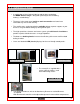
Ovens using 60cm x 40cm trays ( FG156 2 tray / FG158 4 tray) Open the oven door and remove internal racking from sides of oven. (lift and unlatch racking). This allows access to hidden areas in the oven, which can be wiped with a damp cloth. Wipe down, and clean racking with a damp cloth and replace. 4 tray ovens The inner door glass is hinged to enable cleaning of internal surfaces. To open, remove the two screws shown in the sketch below.
9. 7.0 IDEAL OPERATING CONDITIONS • Room should be allowed for the door to open fully to allow easy loading and unloading of product without people coming in contact with hot surfaces. • Racks should be available to allow cooked products to cool safely. • Oven gloves should be available at all times. • It is the customers’ sole responsibility to arrange adequate ventilation and it should be sufficient to ensure water does not condense on or around the oven.
Bx CLASSIC Operating Instructions Section 8 Bx oven CLASSIC HAL range inc condenser 01/12 RAC 13
8.0 BX‘CLASSIC’ OPERATING INSTRUCTIONS RUNNING PRE-SET PROGRAMS REFER TO CONTROL PANEL (SEE RIGHT) 1 2 3 Switch on power by pressing green button (1). Select required program using UP/ DOWN scroll keys (2). Press START key (3) to begin bake cycle. • Oven will heat to set temperature and display will flash actual temperature. • When set temperature is reached the display will stop flashing. The oven is now ready 4 Load product. Close door. 5 Press START key (3).
9.0 BX 'CLASSIC' PROGRAMMING INSTRUCTIONS CREATING PROGRAMS/CHANGING PROGRAM VALUES. Pre-set values for bake temperature; bake time, steam and (optional) damper may be modified at any point. CREATING PROGRAMS/CHANGING PROGRAM VALUES CREATING/CHANGING PROGRAM VALUES 1.Switch on power by pressing green button (1). 2.Use the UP/DOWN arrow keys (2) to select a program to change 3.Press the key associated with the change required (temperature (9), time (8), steam (7), damper (6)).
SETTING PREBAKE TEMPERATURE (if enabled) Press (9). (one dot flashes) Press (9) and hold for 3 seconds (3 dots flash). Use up/down arrow keys (2) to set temperature. Press (9) to save Pre-set values for bake temperature; bake time, steam, sleep mode etc. may be modified at any point. FAN DELAY ENABLING NOTE: This facility is only functional on a 3 phase oven. If it is activated on a1 phase, the fan will stop. Hold the P key (5), together with the STOP key (4) for 5 seconds.
TEMPERATURE SET POINT/CHAMBER DISPLAY Hold the P key (5), together with the STOP key (4) for 5 seconds. or if already done for above setting, continue by pressing start (3) - “dsp” is displayed press (8) to change between “sp” = set point temperature displayed or “ct” = chamber temperature displayed. Pressing start (3) again sets the display back to normal operating mode. PROGRAM “0” ENABLE (Temperature and time only control) Hold the P key (5), together with the STOP key (4) for 5 seconds.
10.0 MAINTENANCE • Check for frayed or bare cables. The machine must not be used if frayed or bare cables are visible. • Follow cleaning instructions. 11.0 STEAM SYSTEM MAINTENANCE • If it is noticed that the steaming operation has deteriorated, perhaps due to hard water scaling, please contact your oven supplier 12.0 STEAM SYSTEM MAINTENANCE 12.
13 CONDENSER UNIT (IF FITTED) All versions should be part of a regular cleaning schedule. Water should be drained and parts cleaned with an antibacterial wash.
INDEX INTRODUCTION PAGE 19 DIMENSIONS PAGE 20 SPECIFICATIONS PAGE 21 INSTALLATION PAGE 22 SAFETY PAGE 24 OPERATION PAGE 25 SPARES PAGE 26 OTHER VERSIONS THAT MAY BE FITTED PAGE 29 ELECTRICAL INFORMATION Bx oven CLASSIC HAL range inc condenser 01/12 RAC SEE ELECTRICS MANUAL 20
INTRODUCTION The condenser can be fitted to any Bx oven or stacked Bx ovens as required. With thermostatic control it can be adjusted to operate in most ambiant temperatures. Simple water conection (washing machine type fitting) and a hose to drain are all that is required to operate efficiently. Steam is drawn from the fluepipe of the oven through a thermostatically controlled water cooled chamber and condenses to drain away.
DIMENSIONS Bx oven CLASSIC HAL range inc condenser 01/12 RAC 22
SPECIFICATIONS POWER 230volts, 1 phase, 50hz, 21watts Wired to oven electrical panel. WATER Washing machine type connection to normal water supply via steam water connection to oven(s).
INSTALLATION BEFORE INSTALLING ENSURE THAT ALL POWER IS DISCONNECTED AND THE OVEN IS COOL 1. Before fitting the main condenser assembly, insert blanking plug (1) into lower hole that will not be required for the hand of oven being used. 2. Connect tube (2) to the spigot and retain with worm-drive clip (3). NOTE If fixing holes are not present on the top sheet of the oven, they should be marked and drilled at this stage. Position condenser correctly and mark hole positions (centre of each slot ).
3. Place condenser in position ensuring that the tube (2) passes through the hole in the top of the oven and worm drive clip (4), then over spigot of the damper assembly on the oven. 4. Tighten worm-drive clip (4). 5. Fasten condenser unit to top of oven with M6 x 12mm long hex head screws and washers in 4 positions. (If holes have been drilled, nuts will have to be used also). 6. Connect wiring, depending on whether the oven is 4 tray or 10 tray, as shown in electrical section of this manual. 7.
SAFETY BEFORE INSTALLING ENSURE THAT ALL POWER IS DISCONNECTED AND THE OVEN(S) IS COOL 1. All repairs and maintenance of electrical units must be carried out by authorised electricians; even then, electrical access panels must not be opened unless the mains supply to the oven is isolated. 2. All connections to the oven must be made in accordance with the statuary requirements of the country of installation. 3. All versions should be part of a regular cleaning schedule.
OPERATION SETTING POSITION 1. 2. Ensure that the water is connected correctly and the oven power is on. The thermostat control should be adjusted to the required position. It is suggested that as a starting point the thermostat is set at 60. It can then be adjusted down if the performance drops or adjusted up if it is found that the water is being replaced too often.
CONDENSER SPARES INFORMATION FOR ENGINEERS USE ONLY. DO NOT ATTEMPT ANY ALTERATIONS.
CONDENSER UNIT MAIN PARTS Bx oven CLASSIC HAL range inc condenser 01/12 RAC 29
ITEM PART No.
OTHER VERSIONS THAT MAY BE FITTED The following evaporation design versions could be fitted to your oven. They only require to be plugged in to the socket found to the rear of the oven. This powers the fan and evaporation pad. No drain is required.
Bx oven CLASSIC HAL range inc condenser 01/12 RAC 32
Bx oven CLASSIC HAL range inc condenser 01/12 RAC 33
Bx oven CLASSIC HAL range inc condenser 01/12 RAC 34
Bx oven CLASSIC HAL range inc condenser 01/12 RAC 35
Bx oven CLASSIC HAL range inc condenser 01/12 RAC 36
Bx oven CLASSIC HAL range inc condenser 01/12 RAC 37
If a fault arises, please do not hesitate to contact the Customer Service Department, quoting the machine serial number on the silver information plate of the machine and on the front cover of this manual MONO Queensway Swansea West Industrial Estate Swansea. SA5 4EB UK . email:spares@monoequip.com Web site:www.monoequip.com Tel. 01792 561234 Spares 44+(0)1792 564039 Fax. 01792 561016 OVEN DISPOSAL CARE SHOULD BE TAKEN WHEN THE MACHINE COMES TO THE END OF ITS WORKING LIFE.