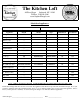
The Kitchen Loft 90 Wood Street Lynbrook, NY 11563 Tel/Fax: 516/599-5946 www.StephenWangel.
PGCS1PJXSS - GE Profile™ 20.7 Cu. Ft. Refrigerator with Armoire Styling - Product ... SEARCH Page 1 of 3 Select Category Shopping Cart | Where To Buy HOME PRODUCTS SERVICE & SUPPORT DESIGN CENTER GE Profile™ 20.7 Cu. Ft. Refrigerator with Armoire Styling Model#: PGCS1PJXSS Print This Page Features & Photos Product Details Parts & Related Products Product Documentation APPROXIMATE DIMENSIONS (HxDxW) 69 5/8 in x 31 in x 35 3/4 in CAPACITY Total Capacity (cubic feet) 20.
PGCS1PJXSS - GE Profile™ 20.7 Cu. Ft. Refrigerator with Armoire Styling - Product ...
PGCS1PJX GE Profile™ 20.7 Cu. Ft.
PGCS1PJX GE Profile™ 20.7 Cu. Ft. French Door Refrigerator with Double Freezer drawers and External Water Air Clearances Overall Dimensions Dimensions and Installation Information (in inches) Height to top of hinge (in.) A 69-5/8 Height to top of case (in.) B 69 Case depth without door (in.) C 23-7/8 Case depth less door handle (in.) D 28-1/2 Case depth with door handle (in.) E 31 Depth with fresh food door open 90° (in.) F 43-1/8 Width (in.) G 35-3/4 Width with door open 90° inc.
PDWF580PSS - GE Profile™ Dishwasher with SmartDis... Page 1 of 3 Monday, February 23, 2009 SEARCH Select Category Shopping Cart | Where To Buy HOME PRODUCTS SERVICE & SUPPORT DESIGN CENTER GE Profile™ Dishwasher with SmartDispense™ Technology Model#: PDWF580PSS Print This Page Features & Photos Product Details Parts & Related Products Product Documentation $1449 Est.
PDWF580PSS - GE Profile™ Dishwasher with SmartDis... Page 2 of 3 Monday, February 23, 2009 SpeedCycle™ (Wash and Dry) DeepClean™ Hand/Gentle Plastics Rinse Only / Hold Number of Options 6 Dishwasher Options Delay Start 1-24 Hr.
PDWF580PSS - GE Profile™ Dishwasher with SmartDis... Page 3 of 3 Monday, February 23, 2009 Upscale Flush Design Door Appearance Stainless steel one-piece contour door Control Panel Color Black WEIGHTS & DIMENSIONS Approximate Shipping Weight 115.00 lb Net Weight (lbs.) 110.00 lb Overall Height 34 in Height w/Legs Extended (in.) 35 Overall Depth 24 3/4 in Overall Width 24 in POWER / RATINGS Calrod Heater Watts 875 Max. Volts/Hertz/Amps 120V ; 60 Hz ; 9.
PDWF500/580P GE Profile™ Dishwasher with SmartDispense™ Technology Dimensions and Installation Information (in inches) Electrical Rating Voltage AC.......................................................... Hertz..................................................................... Total connected load amperage............. Calrod® heater watts max......................... 25-1/4 MAX. 120 60 9.
PDWF500/580P GE Profile™ Dishwasher with SmartDispense™ Technology Features and Benefits • SmartDispense™ Technology - Holds up to 47 fl. oz.
PSB2201NSS - GE Profile Advantium® Wall Oven - Pro... Page 1 of 3 Monday, February 23, 2009 SEARCH Select Category Shopping Cart | Where To Buy HOME PRODUCTS SERVICE & SUPPORT DESIGN CENTER GE Profile Advantium® Wall Oven Model#: PSB2201NSS Print This Page Features & Photos Product Details Parts & Related Products Product Documentation $2349 Est. Retail Price Current Rebate APPROXIMATE DIMENSIONS (HxDxW) 19 1/32 in x 21 1/2 in x 29 25/32 in CAPACITY Total Capacity (cubic feet) 1.
PSB2201NSS - GE Profile Advantium® Wall Oven - Pro...
PSB2201NSS GE Profile Advantium® 240 Wall Oven Note: Cabinets installed adjacent to wall ovens must have an adhesion spec of at least a 194°F temperature rating. Note: 2" minimum between cutouts when installed above warming drawer or single wall oven. Installation Information: Before installing, consult installation instructions packed with product for current dimensional data.
PSB2201NSS GE Profile Advantium® 240 Wall Oven Preparation WITH an Accessory Drawer Prepare the opening The Advantium 240V can be installed in combination with other GE/Monogram appliances. Always follow each product's Installation Instructions to compete the installation. Single Advantium 240V Installation: Order a 30" wide single oven cabinet or cut the opening in a wall to the dimensions shown. * For existing cutouts, a 23-1/2” 30” maximum width of 28-1/2" is acceptable.
PSB2201NSS GE Profile Advantium® 240 Wall Oven Features and Benefits • Speedcook Technology - Cooks up to 8 times faster than a conventional oven OVEN MICROWAVE CONV • 4 Ovens in 1 to Meet Your Cooking Needs - Speedcook, True European Convection, Warming/Proofing, Sensor Microwave SPEED COOK BAKE BROIL COOK CUSTOM WARM PROOF DEFROST SPEED COOK EXPRESS REHEAT FAVORITE RECIPES TIMER START PAUSE CLEAR OFF BACK HELP POWER TEMP OPTIONS • Optimizes cook time for consistent results • Saves valu
Installation Preparation ELECTRICAL REQUIREMENTS INSTALL JUNCTION BOX Single Speedcook Installation The conduit is located at the top right on the back of the oven. Product rating is 120/208 or 120/240 volt, 60 Hz, 30 amps. This product must be connected to a supply circuit of the proper voltage and frequency and protected by a time delay fuse or circuit breaker. Power should be supplied from a separate, dedicated 30-ampere branch circuit.
Installation Preparation Preparation WITHOUT an Accessory Storage Drawer PREPARE THE OPENING (CONT.) PREPARE THE OPENING (CONT.) Installation over a GE/Monogram Oven: Installation over a GE/Monogram Oven and Warming Drawer: 30” 23-1/2” 25-1/4” 17-1/2” Construct Solid Bottom Min. 3/8” Plywood Supported by 2x4 or 2x2 Runners all Four Sides 30” 23-1/2” 25-1/4” 2” Min. (3” recommended) 17-1/2” Per Oven Requirement Construct Solid Bottom Min.
Installation Instructions 1 REMOVE THE PACKAGING AND PARTS • Remove all packing material and tape. • Locate parts package containing mounting screws. • Remove the oven from the carton. Do not lift unit by handle or conduit. Two people are required to lift this oven. • Open the door and remove any packaging in oven.
Installation Instructions 2 ROUTE CONDUIT THROUGH CUTOUT (CONT.) 2 ROUTE CONDUIT THROUGH CUTOUT CAUTION: Two people are required to lift When connecting to a 3-conductor branch circuit: • Connect oven red lead to branch circuit red lead. • Connect oven black lead to branch circuit black lead. • Connect oven green ground lead and white lead to branch circuit neutral (white or gray). the oven into the opening. Grasp the bottom at front and rear. Discard foam base.
Installation Instructions 4 INSTALL MOUNTING SCREWS 3 INSTALL BOTTOM TRIM NOTE: If installing the Advantium 240 Oven with an accessory storage drawer, the bottom trim is not required. Proceed to Step 4. • Align bottom trim tabs to slots in the bottom of the oven. • Slide the oven the remaining way into the opening so that the side flanges and control panel are against the cabinet frame. Make sure that the oven is centered in the opening.
PHP900SMSS - GE Profile™ 30" Electric Induction Cooktop - Product Details SEARCH Page 1 of 2 Tuesday, February 24, 2009 Select Category Shopping Cart | Where To Buy | en español HOME PRODUCTS SERVICE & SUPPORT DESIGN CENTER GE Profile™ 30" Electric Induction Cooktop Model#: PHP900SMSS Print This Page Features & Photos Product Details Parts & Related Products Product Documentation $2049 Est.
PHP900SMSS - GE Profile™ 30" Electric Induction Cooktop - Product Details Power Level Indicator Page 2 of 2 Tuesday, February 24, 2009 Digital 7 Segment APPEARANCE Color Appearance Stainless Steel Frame Color / Material Stainless Steel WEIGHTS & DIMENSIONS Approximate Shipping Weight 46.00 lb Cooktop Size (in.) 30.00 in Cutout Dimensions (Width x Depth) (In.) 28-1/2 x 19-5/8 Net Weight (lbs.) 41.
PHP900SM GE Profile™ 30" Electric Induction Cooktop Features and Benefits • Induction Elements - Powerful yet precise induction elements generate heat directly to the cookware leaving the unused portion of the element unheated and easier to clean • 11" Element - Offers a large 11" surface, wide enough to handle bigger pots and pans and accommodate family meals of any size • 11" Element - At it's highest setting, the 11" element has 3700 watts of power, providing an incredibly fast time to boil water • Elect
PHP900SM GE Profile™ 30" Electric Induction Cooktop Dimensions and Installation Information (in inches) KW Rating 240V 8.6 208V 6.5 Breaker Size 240V 40 Amps† 208V 40 Amps† † Note: Check local codes for required breaker size Important: Requires a 5" free area between the bottom of the cooktop to any combustible material, i.e., shelving. Free area not required when installing wall oven underneath cooktop. Refer to installation instructions.
Installation Instructions PRE-INSTALLATION CHECKLIST ADVANCE PLANNING BEFORE YOU BEGIN Combination Installations WARNING – The electrical power to These cooktops may be installed in combination with an approved downdraft vent or a single oven. the cooktop supply line must be shut off while connections are being made. Failure to do so could result in serious injury or death. A When preparing cooktop opening, make sure the inside of the cabinet and the cooktop do not interfere with each other.
Installation Instructions PREPARING THE OPENING 1 3 VERTICAL CLEARANCES (CONT.) The following MINIMUM clearance dimensions must be maintained. 13″ MAX. Depth of uprotected overhead cabinets IMPORTANT: To ensure long life of the electronic components, allow a minimum of 12″ free space for air circulation below the cooktop bottom. (Except installation over a single oven.) The cooktop bottom has air intake ports toward the front that help cool the components.
Installation Instructions INSTALLING OPTION—FOR GE MONOGRAM MONOGRAM INDUCTION COOKTOP AND MONOGRAM DOWNDRAFT VENT COMBINATION INSTALLATION ONLY. COOKTOP REQUIREMENTS The countertop must have a deep flat surface to accommodate the cooktop and vent. Countertops with a rolled front edge and backsplash will not provide the flat surface area required. The installation of the downdraft vent with this cooktop requires careful consideration.
Installation Instructions INSTALLING OPTIONS COOKTOP INSTALLATION OVER A GE OR GE MONOGRAM SINGLE OVEN POWER SUPPLY The oven requires a separate, properly grounded 20 Amp, 3-wire 208 or 240 volt, 60 Hz power supply. The cooktop requires a separate 40 Amp, 3-wire, 208 or 240 volt, 60 Hz power supply. These cooktops may be installed over a single oven. Both the cooktop and the oven must be installed according to each specific installation instruction. – Allow 4″ Min.
Installation Instructions ELECTRICAL CONNECTIONS THREE-CONDUCTOR BRANCH CIRCUIT CONNECTION NEW CONSTRUCTION AND BRANCH CIRCUIT CONNECTION When connecting to a three-conductor branch circuit, if local codes permit: WARNING: Improper connection of aluminum house wiring to copper leads can result in an electrical hazard or fire. Use only connectors designed for joining copper to aluminum and follow the manufacturer’s recommended procedure closely. a.
Installation Instructions INSTALLING THE COOKTOP 3 ATTACH FOAM TAPE 1 PROTECT SURFACE OF COOKTOP Apply the foam tape around the outer edge of the glass. Do not overlap the foam tape. Place a towel or tablecloth onto the countertop. Lay the cooktop upside down onto the protected surface. Bottom of Cooktop Bottom of Cooktop Foam Tape Cooktop Glass NOTE: On stainless steel models, apply foam tape on the sides and rear.
Installation Instructions 5 INSERT COOKTOP INTO CUTOUT 6 ATTACH HOLD-DOWN BRACKETS TO CABINET Insert the cooktop centered into the cutout opening. Make sure the front edge of the countertop is parallel to the cooktop. Make final check that all required clearances are met. Open the cabinet door. Install the second screw through the bracket and tighten. Then tighten the first screw. Install thumbscrew until it touches the bottom of the countertop.
Installation Instructions CHECKLISTS 1 PRE-TEST CHECKLIST 2 OPERATION CHECKLIST A Remove all protective film, if present, and any stickers. A Remove all items from the top of the cooktop surface. B Check to be sure that all wiring is secure and not pinched or in contact with moving parts. B C Check level of appliance. Turn on the power to the cooktop. (Refer to your Owner’s Manual.) Verify that all surface burners operate properly. D Check that the cooktop is properly grounded.
PT916SMSS - GE Profile™ 30" Built-In Single Convectio... Page 1 of 3 Monday, February 23, 2009 SEARCH Select Category Shopping Cart | Where To Buy HOME PRODUCTS SERVICE & SUPPORT DESIGN CENTER GE Profile™ 30" Built-In Single Convection Wall Oven Model#: PT916SMSS Print This Page Features & Photos Product Details Parts & Related Products Product Documentation $2449 Est.
PT916SMSS - GE Profile™ 30" Built-In Single Convectio...
Cabinetry A Cutout for 30″ (76.2 cm) Single Ovens only – Below an Advantium or Microwave Oven or Between an Advantium or Microwave Oven and a Warming Drawer For JTP30, JTP70, PT916, PT920, ZET938 models only. Single 30″ (76.2 cm) Oven Below an Advantium or Microwave Oven Per Advantium or Microwave Oven Requirement Single 30″ (76.2 cm) Oven Between an Advantium or Microwave Oven and a Warming Drawer Per Advantium or Microwave Oven Requirement 2” (5.1 cm) Min.
Installation Instructions B Electrical Connections ATTENTION INSTALLER All electric wall ovens must be hard wired (direct wired) into an approved junction box. A plug and receptacle is NOT permitted on these products. DO NOT shorten the flexible conduit. The conduit strain relief clamp must be securely attached to the junction box and the flexible conduit must be securely attached to the clamp.
Installation Instructions B3 New Construction and Four-Conductor Branch Circuit Connection B4 Three-Conductor Branch Circuit Connection When connecting to a three-conductor branch circuit, if local codes permit: • When installing in new construction, or a. Connect the bare oven ground conductor with the crimped neutral (white) lead to the branch circuit neutral (white or gray in color), using a wire nut.
Installation Instructions C Securing the Oven in the Opening C1 Sliding the Oven Into the Opening C2 Drilling the Pilot Holes and Mounting the Oven a. Loop (do not tie) a 36” (91 cm) string around the conduit before the oven is slid into place. This will keep the conduit from falling behind the oven. NOTE: Before drilling the pilot holes, make sure the oven is pushed as far back into the opening as it will go and centered. a.
Installation Instructions C3 Preparing for the Bottom Trim Installation C4 Installing the Metal Bottom Trim a. With oven installed, take the bottom trim and center it on the bottom front edge of the cabinet opening. a. Place the bottom metal trim centered over the pre-drilled mounting holes. Tape the edges of the trim down to maintain the alignment. b. Using the trim as a template, mark the center of each slot (two total) where the mounting holes will be drilled. c. Remove the trim. d.
Installation Instructions D Replacing the Oven Door NOTE: The oven door is heavy. You may need help lifting the door high enough to slide it into the hinge slots. Do not lift the door by the handle. D1 D3 Open the oven door as far as it will open. D4 Push the hinge locks up against the front frame of the oven cavity, to the locked position. Hinge in Locked Position Lift the oven door by placing one hand on each side. The door is heavy, so you may need help. Do not lift the door by the handle.
Cutout width 28-1/2'' MIN. 28-5/8'' MAX. ™ PT916SM 5 GE Profile 30" Built-In Single Convection Wall Oven Dimensions and Installation Information (in inches) 23-1/2'' MIN. Cutout depth Junction KW Rating box location 240V 4.5 A 208V 3.4 Breaker Size CL 2 x 4 or equivalent runners B 240V 20 Amps 22'' MIN. 27-1/4'' MIN. Conduit 208V 20 Amps 27-5/16'' MAX. (72" long) Cutout height Most 30” Wall Cabinets can be used with this unit. 21 Cutout width 28-1/2'' MIN. 28-5/8'' MAX.
PT916SM GE Profile™ 30" Built-In Single Convection Wall Oven Optional Undercounter Dimensions and Installation Information Note: 36” ribbon cooktops are approved for use over GE 30” single wall ovens only. 30” ribbon cooktops are approved for use over GE 30” and GE 27” single wall ovens. Refer to cooktop and wall oven installation information packed with products for current dimensional data.
PT916SM GE Profile™ 30" Built-In Single Convection Wall Oven Features and Benefits • Glass Touch Controls - Features a smooth glass design that is easy-tooperate and easy-to-clean • Precise Air™ Convection System - Provides even air and heat circulation for superior baking and roasting results • Flat Back Convection - Features a more streamline convection fan that better accommodates baking or roasting pans • Convection Bake - Delivers ideal airflow throughout the oven cavity, ensuring better baking res
ZV830SMSS - GE Monogram® 30" Wall-Mounted Vent Hood - The GE Monogram Collection Page 1 of 2 Tuesday, February 24, 2009 GE Monogram® 30" Wall-Mounted Vent Hood Model#: ZV830SMSS Print This Page Features & Photos Product Details Parts & Related Products Manuals & Documentation FEATURES Photo Gallery Manuals & Documentation Requires Adobe® Reader® Feature Reference Guide Installation_Instructions Quick_Specs Use_and_Care_Manual CAD Download ENERGY STAR® Qualified No Blower Levels 4 Control Type
ZV830SMSS - GE Monogram® 30" Wall-Mounted Vent Hood - The GE Monogram Collection Overall Depth Page 2 of 2 Tuesday, February 24, 2009 25 in POWER / RATINGS Amp Rating at 120V 12.
ZV830SM GE Monogram® 30" Wall-Mounted Vent Hood Features and Benefits • Stainless Steel Design - Creates a striking architectural impression with bold angles and smoothly finished edges • Powerful Ventilation - Offers three speeds plus a 500-cfm boost to capture cooking fumes produced by 30" cooktops - FAN + - LIGHT + • Perimeter Filter System - Draws fumes and vapors around a stainless steel center panel, which completely and stylishly conceals filters • Halogen Lighting - Provides four levels of cl
ZV830SM GE Monogram® 30" Wall-Mounted Vent Hood 10-7/8 Dimensions and Installation Information (in inches) This vent hood is designed to be installed on a wall and vented to the outdoors, or it can be installed for recirculating operation. All necessary parts for recirculating operation are supplied with the hood. No kits required. Must use an 8" round duct, not supplied with product. A decorative duct cover is provided to enclose the duct from the top of the hood to a 8' to 10' ceiling.
Installation Preparation DUCT FITTINGS This Hood Must Use an 8″ Round Duct. It Can Transition to a 3-1/4″ x 12″ Duct. Use this chart to compute maximum permissible lengths for duct runs to outdoors. Duct Piece Dimensions Round, straight 3-1/4″ x 12″ straight Equivalent Length* 1 ft. (per foot length) Total Quantity Equivalent Used Length 1 ft. (per foot length) 90° elbow NOTE: Do not exceed maximum permissible equivalent lengths! 17 ft. 45° elbow Maximum duct length: 100 feet for range hoods.
Installation Preparation DETERMINE INSTALLATION HEIGHT Wall Mount ZV830 Installation Heights 24” Min. 30” Max. 36” Min. NOTE: Installation height should be measured from the cooking surface to the lowest part of the hood. The vent hood must be installed 24″ min. and 30″ max. above the cooking surface. The hood installation height, from the cooking surface to the bottom of the hood, depends upon ceiling height. ACCESSORIES: ZX83012 Accessory duct cover is available for 10 ft. to 12 ft. ceilings.
Installation Preparation CHECK INSTALLATION HARDWARE Locate the hardware package packed with the hood and check contents.
Installation Instructions INSTALLATION—VENTED TO THE OUTSIDE 1 INSTALL FRAMING FOR HOOD SUPPORT DUCTWORK, WIRING LOCATIONS Determine the exact location of the vent hood. • Locate the template packed with the literature. – Measure 36″ from the floor to the top of the cooking surface. Add hood installation height determined on page 7. Mark that location. – Use a level to draw a straight pencil line on the wall. 5-1/2” centerline to wall of supporting 100 lbs. 8" Min. Opening for Ductwork 8-1/2” min.
Installation Instructions INSTALLATION—VENTED TO THE OUTSIDE 2 INSTALL HOOD MOUNTING SCREWS 4 MOUNT THE HOOD WARNING: 2 people are required to lift and position The two upper mounting screws must enter the horizontal support or wall studs. • With the template taped in place, use a punch to mark mounting bracket screw locations. • Drill 1/8″ pilot holes in 2 of the punched locations in the lower bracket. • Remove the template.
Installation Instructions INSTALLATION—VENTED TO THE OUTSIDE 5 CONNECT DUCTWORK • Remove shipping tape from the damper. • Install ductwork, making connections in the direction of airflow as illustrated. • Push duct over the exhaust outlet and damper. • Secure joints in ductwork with sheet metal screws. • Wrap all duct joints and the flange connections with duct tape for an airtight seal. Airflow Duct tape over seam and screw Screw CAUTION: Do not use sheet metal screws at the hood flange connection.
Installation Instructions INSTALLATION—VENTED TO THE OUTSIDE 6 CONNECT ELECTRICAL 7 INSTALL DUCT COVERS • Remove protective plastic Mounting covering. screws • Place the decorative duct covers on top of the hood. NOTE: The inside duct piece has vent holes on one end. The holes are intended for use when the hood is installed for recirculating purposes. Slide the inside end into the outer piece; the vent holes should not be visible in this installation. Verify that power is turned off at the source.
Installation Instructions INSTALLATION—VENTED TO THE OUTSIDE 8 INSTALL FILTERS 9 FINALIZE INSTALLATION IMPORTANT: Check to be sure that the main ON/OFF switch next to the motor is in the ON position. • Check to be sure all tape and packaging materials have been removed. • Refer to the Owner’s Manual for operating instructions. Push-button switch (horizontal view from inside opening) • Remove protective films on the grease filters and filter cover panel.